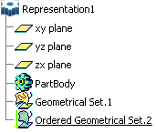
Generative Shape Design Specification Tree

This section contains the list of all Generative Shape Design Specification Tree symbols.

Tree Structure

The following picture represents a typical Shape Design specification tree:


Symbols

General


3D Shape Representation    


Managing Geometrical Sets    


Managing Ordered Geometrical Sets    


Sketch    


Selecting Using the Multi-Selection    
Wireframe


Creating Points

Creating Parallel Curves


Creating Multiple Points and Planes

Creating a Rolling Offset


Creating Extremum Elements

Creating a 3D Curve Offset


Creating Polar Extremum Elements

Creating Circles


Creating Lines

Creating Power Copies


Creating an Axis

Creating Connect Curves


Creating Polylines

Creating Conic Curves


Creating Planes

Creating Splines


Creating Projections

Creating a Helix


Creating Combined Curves

Creating Spirals


Creating Reflect Lines

Creating a Spine


Creating Intersections

Creating Isoparametric Curves on Surfaces
Law


Creating Laws    
Surfaces


Creating Extruded Surfaces

About Swept Surfaces


Creating Revolution Surfaces

Creating Adaptive Swept Surfaces


Creating Spherical Surfaces

Creating Fill Surfaces


Creating Cylindrical Surfaces

Working with Multi-Sections Surfaces


Creating Offset Surfaces

Creating Blended Surfaces


Creating Variable Offset Surfaces    


Creating Rough Offset Surfaces    
Operations  


Joining Surfaces or Curves

Translating Geometry


Healing Geometry

Rotating Geometry


Smoothing Curves

Performing a Symmetry on Geometry


Restoring a Surface or Curve

Transforming Geometry By Scaling


Splitting Geometry

Transforming Geometry by Affinity


Trimming Geometry

Transforming Elements from an Axis to Another


Creating Boundaries

Extrapolating Curves


Extracting Elements

Inverting the Orientation of Geometry


Extracting Sub-Elements

Creating the Nearest or the Farthest Entity of a Multiple Element


Creating Bitangent Shape Fillets    


Creating Edge Fillets    


Creating Variable Radius Fillets    


Creating Face-Face Fillets    


Creating Tritangent Fillets    
Replication


Creating Rectangular Patterns

Creating Planes Between Other Planes


Creating Circular Patterns

Managing Power Copies


Creating User Patterns    
Advanced Surfaces


Creating Bumped Elements    


Deforming Elements According to Curve Wrapping    


Deforming Elements According to Surface Wrapping    


Deforming Elements According to Shape Morphing    
Developed Shapes


Unfold    


Developing Wires and Points    
Volumes


Creating Extruded Volumes

Creating a Shell


Creating Revolution Volumes

Creating a Sew Surface


Creating Multi-Sections Volumes

Creating Thicknesses


Creating Swept Volumes

Adding Volumes


Creating a Thick Surface

Removing Volumes


Creating a Close Surface

Intersecting Volumes


Creating a Draft

Trimming Volumes


Creating a Variable Draft Angle    


Creating a Draft from Reflect Lines    
BiW Templates


Creating Junctions

Creating a Hole Curve


Creating a Diabolo

Creating a Mating Flange


Creating a Hole

Creating a Bead


Creating 2D-View Sections

Creating a Blend Corner
Tools


Defining an Axis System

Creating Masks


Working with a Support Working with a 3D Support

Creating Datum Elements


Creating Plane Systems    
Analysis


Checking Connections Between Surfaces

Analyzing Surfacic Curvature


Checking Connections Between Curves

Analyzing Using Porcupine Curvature


Analyzing Draft Angle    

Masks


Federated: the element has been federated (this mask is only available with the Joining Surfaces or Curves, Extracting Elements and Extracting Sub-Elements commands).
Further information on general masks in the specification tree are available in refer to Part Design User's Guide:Interface Description: Masks.