Splitting Geometry | ||||||||
|
| |||||||
Split Two Elements
You can split elements by selecting a cutting element.
Click Split
 in the Operation toolbar.
The Split Definition dialog box appears as well as the Tools Palette. For more information about the Tools Palette, refer to Infrastructure User's Guide: Selecting Using Selection Traps.
In the Element to cut box, select the element to be split.
You should make your selection by clicking on the portion that you want to keep after the split.
You can select several elements to cut. In that case, click Element to cut again or click
 .
The Elements to cut dialog box appears. Select as many elements
as needed. Click Close to return to the Split Definition
dialog box. The number of selected elements is displayed in the Element to cut box
.
The Elements to cut dialog box appears. Select as many elements
as needed. Click Close to return to the Split Definition
dialog box. The number of selected elements is displayed in the Element to cut box
Click Remove or Replace to modify the elements list. When several elements to cut are selected, the selected portions are not taken into account as parts to keep. The parts to be kept depend on the type of the cutting element (point, curve, surface, etc.) and the orientation of cutting elements and the elements to cut. Click Other side to reverse the portion to be kept, element by element.
In the Cutting elements area, select the cutting element.
A preview of the split appears. You can change the portion to be kept by selecting that portion.
You can also select the portion to be kept by clicking Other side. This option applies on all selected elements to cut.
Note:
-
You can select several cutting elements. In that case, note that the selection order is important as the area to be split is defined according to the side to be kept in relation to the current splitting element.
-
Right-click in the Cutting elements and select Create Join to create a join as the splitting element. If you split a surface and you keep both sides by joining the resulting splits, you cannot access the internal sub-elements of the join. The splits result from the same surface and the cutting elements are common.
-
-
Optional: Click Show Parameters>> to view more options.
Optional: You can select the Keep elements in half space check box to keep all the elements that are on one side of the cutting infinite plane. The cutting element defines this half space.
Warning: - This check box applies only when the cutting element is an infinite plane.
- If the split side is not towards the element to cut, an error message is issued. Note that this behavior differs from the behavior in the Part Design workbench, i.e. no error message is issued.
Elements to cut: dark blue and light blue surfaces ; Cutting elements: yellow and purple planes Result with the Ignore no intersecting elements check box selected
 Element to cut: non connex light blue surface ; Cutting element: yellow plane
 Result with Keep elements in half space check box selected
Warning: Avoid splitting geometry when the intersection between the element to cut and the cutting element is merged with an edge of the element to cut. We advise you to use the Elements to remove and Elements to keep options to remove the positioning ambiguity. Click OK to split the element.
The created element (identified as Split.xxx) is added to the specification tree.
In the case several elements to cut were used, the created elements are aggregated under a Multi-Output.xxx feature.
In the illustrations below, the top-left line is the first splitting element. In the left illustration it defines an area that intersects with the other three splitting curves, and in the illustration to the right, these three elements are useless to split the area defined by the first splitting element.
To remove or replace one of these cutting elements, select it from the list and click Remove or Replace.
![]()
Split a Surface by a Curve or a Surface by a Surface
You can split a surface by selecting a curve or another surface as a cutting element.
Split a surface by a curve
You can extrapolate a curve to split the surface.
The cutting element (the curve) is laid down the
surface.
Extrapolate the curve in tangency.
Warning: When this extrapolation leads to the intersection of the cutting element with itself prior to fully splitting the initial element, an error message is issued as there is an ambiguity about the area to be split. Split the surface by the curve.
| Warning: If the cutting element does not reach the free edges of the element to cut, an extrapolation in tangency is performed using the part of the cutting element that lays down the surface. |
Split a surface by a surface
You can extrapolate a surface to split another surface.
Create an intersection (the green wire) between the two surface elements.
Use the result of the extrapolation as the cutting element to perform the split operation.
Warning: Note that it is not the cutting element which is extrapolated but the result of the intersection. Tip: If the result of the split is not what was expected, it is also possible to manually extrapolate the cutting element with the extrapolate feature before creating the split. Extrapolate the cutting element (the red surface) in order to fully intersect the element to cut.
Use the extrapolated surface as the cutting element to split the surface.
| Warning: Avoid using input elements which are tangent to each other since this may result in geometric instabilities in the tangency zone. |
![]()
Split Volumes
You can split volumes by means of a cutting element.
Warning:
|
Providing the element to be cut is a volume and the cutting element is
a volume or a surface, you can choose whether you want the result of the
split to be a surface or a volume. 
- Select either the Surface or Volume
option.
Note:
- Replacing an input element does not change the result type,
- The switch between surface and volume is grayed out when editing
the feature.
If the result of the split is a volume, the split is a modification
feature. If the result of the split is a surface, the split is a
creation feature.
For more information about volumes, refer to Creating Volumes.
![]()
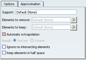
Approximate the Split Result
You can control the quality of the result of the split through several parameters and modes.
Select the Approximation tab.
The dialog box appears as follows:
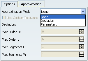
| Important: Note that the approximation is only available for rectangle type surfaces, i.e. for the surfaces which have only four side edges. |