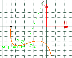
Click Work on Support
 .
.
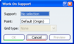
Select the plane to be used as support element.
The Work On Support dialog box is displayed, allowing
you to define the plane:
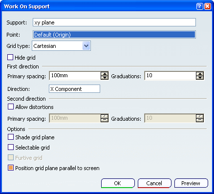
By default, the Grid type is set to Cartesian
to define a Cartesian plane.
Select a point, as the support plane's origin.
By default the plane's origin is selected. Note that the plane
representation may not be located at the plane's origin. In this case,
the default point is displayed at the origin and therefore
not necessarily onto the plane representation.
Define the First direction scale (H for
horizontal), by setting Primary spacing and Graduations
values.
Optional: Select a direction to specify the H direction.
You can right-click in the editable field to display the
contextual menu and define the direction (by defining its vector,
creating a line, and so forth).
If you wish, you can define another scale for the
Second direction (V for vertical), thus allowing
distortions of the grid. Check Allow distortions to activate
the Primary spacing and Graduations fields of the
second direction.
Optional: Select theShade grid plane option to visualize
the support plane as a solid geometric element.
Optional: Select the Selectable grid option
to enable the selection of sub-elements of the grid (lines and points) as
a support for a future selection.
Selected sub-elements are featurized.
Optional: Select the Furtive grid option
to see the grid only when it is parallel to the screen.
Optional: Select the Position grid plane parallel to screen
option
to reset the grid visualization parallel to the screen.
From the Grid sub-toolbar, click Snap to point
 to snap the point being created onto the nearest intersection point on the
grid.
Click OK in the dialog box.
The element (identified as Working support.xxx) is added to the
specification tree.

![]()
![]()
