Create an Offset Surface
You can create a
surface by offsetting an existing surface.
Click Offset
 in the Offsets sub-toolbar. in the Offsets sub-toolbar.
The Offset Surface Definition dialog box appears.
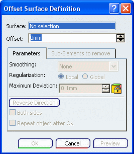
In the Surface box, select the surface to be offset.
An arrow indicates the proposed direction for the
offset.
In the Offset box, type the value or use the arrows to change the value.
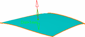
Click Preview
to preview the offset surface.
The offset surface is displayed normal to the reference surface.
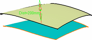
Click OK to create the surface.
The surface (identified as Offset.xxx) is added to the
specification tree.

Remove Sub-Elements
You can remove the sub-elements using the Sub-Elements to remove tab. The Sub-Elements to remove tab helps you for the
analysis in case the offset encounters a problem.
Perform steps 1 to 3 above. Click Preview.
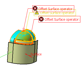
The Warning dialog box appears and informs you that some
sub-elements are erroneous. The geometry shows these sub-elements
and flag notes
display sub-elements to remove.
There are different colored flag notes to display the severity of
errors:
 The red-colored flag shows that the error is critical. The red-colored flag shows that the error is critical.
 The yellow-colored flag depicts warning. The yellow-colored flag depicts warning.
 The white-colored flag shows information regarding the offset. The white-colored flag shows information regarding the offset.
Click Yes to accept the offset.
In the dialog box, the Sub-Elements to
remove tab lists the erroneous sub-elements and a preview of the
offset is displayed.
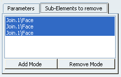
As this list is not always optimal, you can manually add or remove
sub-elements:
- Add Mode:
- When you click an unlisted element in the geometry, it is
added to the list.
- When you click a listed element, it remains in the list.
- Remove Mode:
- When you click an unlisted element in the geometry, the list is
unchanged.
- When you click a listed element, it is removed from the
list.
Click Preview.
The offset surface is displayed normal to the reference surface.
Click OK to create the surfaces.
The surfaces (identified as Offset.xxx) are added to the
specification tree.

Smooth an Offset Surface
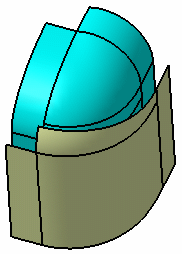
You can apply smoothing on the offset surface.

In the Smoothing list, select the smoothing type on the offset surface:
- None: the smoothing is constant. This is the
default type.
- Automatic: a local smoothing
is applied only if the constant offset cannot be performed. It cleans
the geometry of the surface and enables the offset. A warning message is launched and the modified surface is shown
in the 3D geometry. If a surface still cannot be offset, no smoothing is performed
and a warning message is issued (as in the constant offset mode).
If you click Yes, erroneous sub-elements are removed and the offset operation goes on.
- Manual: a local smoothing is
applied as in the Automatic type. You need to define a Maximum
Deviation below which the elements are to be offset. If the
resulting deviation is greater than the defined deviation, no smoothing
is performed and a warning message is issued (as in the constant offset
mode). If you click Yes, erroneous sub-elements are removed and the offset operation goes on.
Select the Regularization type on the offset surface:
- Local: regularizes the offset surface locally to minimize the deviation.
- Global: regularizes the offset surface completely. If the local regularization fails, by default, the offset surface is globally regularized.
|
![]()
![]()


 The red-colored flag shows that the error is critical.
 The yellow-colored flag depicts warning.
 The white-colored flag shows information regarding the offset.


