Creating a Hole | |||
| |||
Click Hole
 in the BiW Templates toolbar..
The Hole Definition dialog box appears.
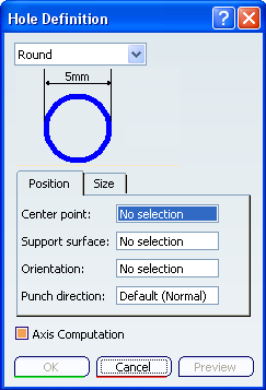
Various shapes can be created:
- round
- slot (elongated hole)
- rectangular
- square
The shape is defined on a plane and projected along a direction on the surface. In that case, the nearest projection is used to create the hole.
Click Preview.
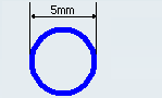
Define the shape dimensions.
To do so, either :
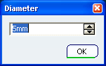
-
click the value to edit (here the diameter).
The Diameter dialog box opens to let you modify the dimension.
-
click the Size tab.
All dimensions related to the selected shape are displayed and can be modified.
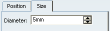
Warning: Some values must be greater than 0mm: - Diameter for the round hole
- Length and width for the slot and rectangle hole
- Length for the square hole
-
Click OK to create the hole.
The element (identified as Type Hole.xxx) is added to the specification tree.
Round hole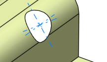 Slot hole
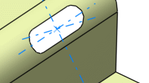 Rectangular hole
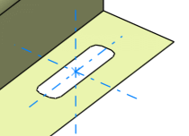 Square hole
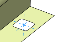
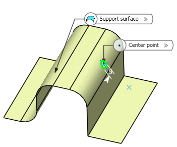
| Warning: If several solutions are possible, the solution with the minimum distance is chosen. If all distances are equal, an error message is issued, asking you to modify the point position. |