Translate Along a Direction and a Distance
You can translate the element by specifying a direction and defining a distance.
Click Translate
 . .
The Translate Definition dialog
box appears as well as the Tools Palette.
For further information about the Tools Palette, refer to Infrastructure User's Guide
: Selecting Using Selection Traps.
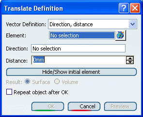
Select the Element to be translated. Select Direction, distance as the Vector Definition. Select a line to take its orientation as the translation
direction or a plane to take its normal as the translation direction.
You can also specify the direction by means of X, Y, Z vector
components by using the contextual menu on the Direction
box.
Specify the translation Distance by entering a
value or using the spinners.
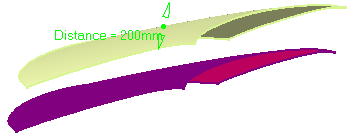
Click OK to create the translated element.
The element (identified as Translate.xxx) is added to the
specification tree.
The original element is unchanged.

Translate Using Two Points
You can translate the element by defing the start and end points.
Click Translate
.
The Translate Definition dialog box
appears as well as the Tools Palette.
For further information about the Tools Palette, refer to Selecting
Using Selection Traps in the Infrastructure User's Guide.
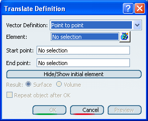
Select the Element to be translated. Select Point to Point as the Vector Definition. Select the Start point. Select the End point.
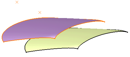
Click OK to create the translated element.
The element (identified as Translate.xxx) is added to the
specification tree.
The original element is unchanged.
Translate Using Coordinates
You can translate the element by defining the coordinates.
Click Translate
.
The Translate Definition dialog box
appears as well as the Tools Palette.
For further information about the Tools Palette, refer to Selecting
Using Selection Traps in the infrastructure User's Guide.
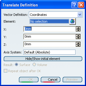
Select the Element to be translated. Define the X, Y, and Z coordinates.
In our example, we chose 50mm as X, 0mm as Y, and -100 as
Z.
When the command is launched at creation, the initial
value in the Axis System box is the
current local axis system. If no local axis system is current, the box
is set to Default. Whenever you select a local axis system, the translated element's
coordinates are changed with respect to the selected axis system so that
the location of the translated element is not changed. This is not the
case with coordinates valuated by formulas: if you select an axis system,
the defined formula remains unchanged.
Click OK to create the translated element.
The element (identified as Translate.xxx) is added to the
specification tree. The original element is unchanged.
|