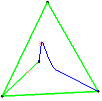
Creating Connect Curves | |||
| |||
The Connect Curve Definition dialog box appears.
Select the Connect type:
-
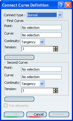
Normal:
-
Base Curve: it is useful when creating several profiles or guides that have the same shape.
Warning: This type is only available with the Generative Shape Design 2 product. 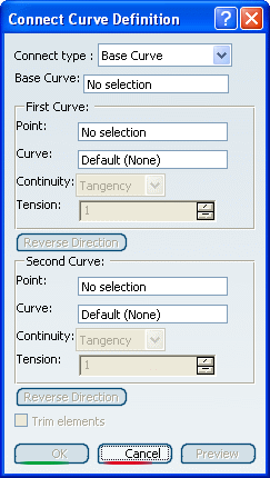
-
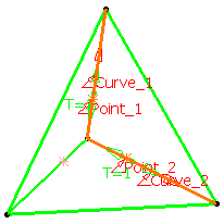
Select a first Point on a curve then a second Point on a second curve if you want to create a Normal connect curve. The Curve fields are automatically filled.
or
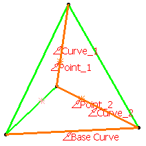
Select a Base Curve as the curve reference and a first Point on a curve then a second Point on a second curve. The orientation of the connect curve will be the orientation of the base curve. Points can be either located on the base curve or on the support curve. The selection of a support curve is optional (it is set as Default).
Use the drop-down lists to specify the desired Continuity type: Point, Tangency or Curvature.
If needed, enter tension values.
A graphic manipulator also allows you to modify the tension at the extremity of the connect curve, rather than in the dialog box.
The connect curve is displayed between the two selected points according to the specified continuity and tension values.Warning: If the Base Curve type is selected, the Continuity and Tension options for the first and the second curve are grayed out and set to Tangency and 1 respectively. Normal curve with point continuity at both points Both tensions = 1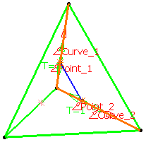 Normal curve with point continuity at first point and tangent continuity at the second point Both tensions = 1
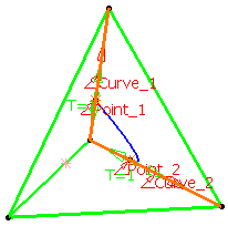 Normal curve with tangent continuity at first point and curvature continuity at the second point Both tensions = 1
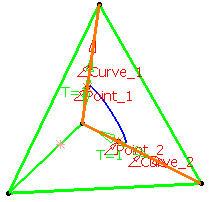 Normal curve with tangent continuity at first point and curvature continuity at the second point First tension = 10 and second tension = 1
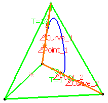
Important: A red arrow is displayed at each extremity of the curve: the orientation of the arrow of the first/second direction corresponds to that of the connect curve's tangent to the first/second selected point. Click the arrow to reverse the orientation of the curve at that extremity or click Reverse Direction.
Important: If the Base Curve type is selected, the Reverse Direction buttons are grayed out. Check the Trim elements option if you want to trim and assemble the two initial curves to the connect curve.
Warning: If the Base Curve type is selected, you must select a support curve to access the Trim elements option. Otherwise, it is grayed out. Click OK to create the connect curve.
The curve (identified as Connect.xxx) is added to the specification tree.
Normal curve with tangent continuity at both points Both tensions = 1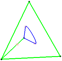 Base Curve Trim elements option checked