Creating Fill Surfaces

You can create fill surfaces between a number of boundary segments.


Before you begin: Create a 3D shape containing curves or surfaces edges.
Related Topics
More about the Fill Command
  1. Click Fill in the Surfaces toolbar.

    The Fill Surface Definition dialog box appears.

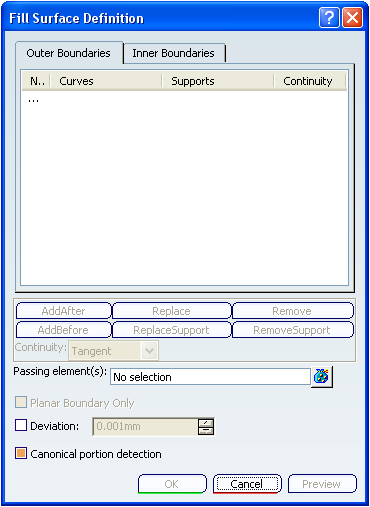
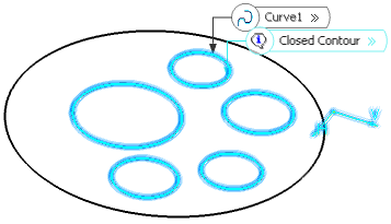
  2. In the Outer Boundaries tab, select curves or surface edges to form the outer closed boundary.

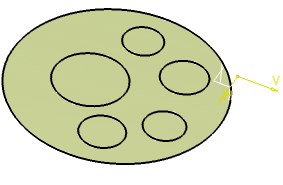
    A diagnosis is displayed in the 3D area and the fill surface is previewed within the boundary.

    Important: You can also create a fill surface without selecting the outer boundaries. You can select any one of the following:
    • Inner boundaries
    • Inner boundaries and passing elements
    • Passing elements (at least three non-collinear points or a curve).

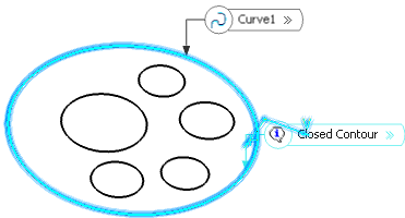
  3. Optional: In the Inner Boundaries tab, select inner curves or surface edges to form the inner closed boundary.


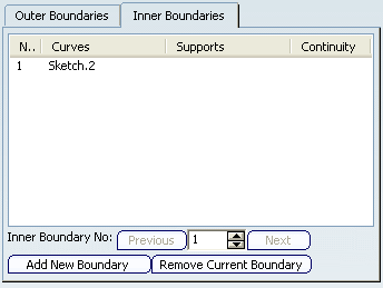
    Note: Only curves corresponding to a single inner boundary are displayed in the list.

    A diagnosis is displayed in the 3D area and the fill surface is displayed within the boundary.


    The resulting surface will be a fill surface between the outer and inner closed boundaries.

    Tip: You can switch from the Outer Boundaries and Inner Boundaries tabs during the selection, however, the diagnosis is displayed only for the curves corresponding to the active tab.

  4. Optional: Click Add New Boundary to add a new boundaries or Remove Current Boundary to remove the selected boundary.

    Important: If you click Add New Boundary, the currently displayed curve is cleared in the list to let select another curve.

  5. Optional: Click Previous or Next buttons to navigate between all inner curves and their supports defining a closed contour.

    When the current boundary is the last one, the Next button is unavailable. Similarly, when it is the first one, the Previous button is unavailable. You can use the spinners to move from one set of curves to another or directly click a number in the box.

  6. Optional: For both tabs, you can select a support surface for each curve or edge. In this case, the continuity will be assured between the fill surface and selected support surfaces.

    Note: You can define a support just after the selection of the curve or by clicking the curve in the list and selecting a support. To be able to select a support, the boundary must fully lie on the support.

  7. Optional: For both tabs, you can select a continuity type for each support surface. You can modify the continuity type either from:

    • the dialog box: select the input in the list and modify the type from the Continuity combo box, or
    • the 3D area: click the widget to switch from one type to another or right-click it and select the type from the contextual menu. Widgets are useful to visualize whether and which continuity is set on a boundary.

  8. Optional: Use the combo to specify the desired continuity type between any selected support surfaces and the fill surface:


    • Point
    • Tangent, or
    • Curvature
    Warning: Inner and outer boundaries cannot intersect, be merged or be the same.

    Note: You can edit outer and inner boundaries by first selecting an element in the dialog box list then clicking a button to either:

    • Add a new element after or before the selected one

    • Remove the selected element

    • Replace the selected element by another curve

    • Replace the selected support element by another support surface

    • Remove the selected support element.

  9. Optional: In the Passing elements box, select one or more points and curves.

    This element can either be a point or a curve through which the filling surface must pass, thus adding a constraint to its creation. However, you may need to alleviate the number of constraints by removing the supports.

    Warning: The passing point should lie within the area delimited by the selected curves. If not, the results may be inconsistent.
    Tip: You can click to display the Passing Element(s) dialog box and modify the selection.

  10. Optional: You can select the Planar Boundary Only check box to fill only planar boundaries, when the boundary is defined by one curve on one surface.

  11. Optional: You can select the Deviation check box and enter a value to fill the existing gaps.

    Important: In the Tools > Options > Shape > Generative Shape Design > General tab,
    • If the Continuity Type is either set to Tangency or Curvature, the Deviation check box is selected by default.
    • The Maximum deviation value is taken as the default deviation value for the fill.
    Warning: The curves should be selected so that there should not be a gap superior to 0.1mm between them. Otherwise, an error message is issued. If the gap between two curves is greater than the maximum deviation, the gap is not filled and the resulting surface still displays a gap.

  12. Click OK to create the fill surface.

    The surface (identified as Fill.xxx) is added to the specification tree.

    Here are complementary examples of filled surfaces:

    Filling surface without specified supports

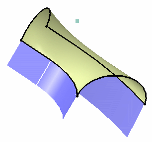
    Filling surface with a passing point and no specified supports

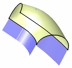
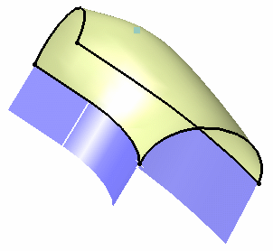
    Filling surface with specified supports (blue and yellow surfaces) and a tangency continuity

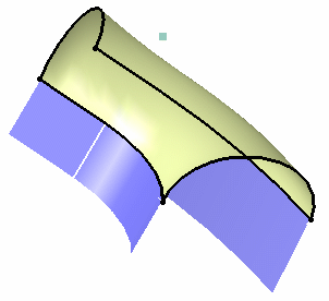
    Filling surface with a passing point, specified supports (blue and yellow surfaces) and a tangency continuity