Click Extract
 .
.
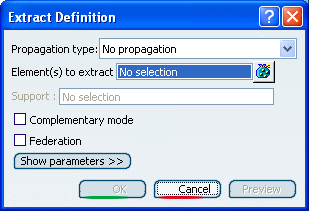
The Extract Definition dialog box appears as well as the Tools Palette. For further information about the Tools Palette, refer to Infrastructure User's Guide : Selecting Using Selection Traps.

In the Part Design
workbench, the Extract capability is available as a
contextual command named Create Extract that you can
access from Sketch-based features dialog boxes.
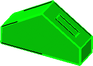
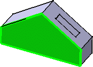
Select an edge or the face of an element.
The selected element is highlighted.
Choose the Propagation
type:
- Point continuity: the extracted element will not
have a hole.

- Tangent continuity: the extracted element will be
created according to tangency conditions.

- Curvature continuity: the
extracted element (necessarily a curve) will be created according
to curvature conditions.

- No propagation: only the selected element will be
created.

Select the Federation check box to generate
groups of elements belonging to the resulting extracted element that
will be detected together with the pointer when selecting one of its
sub-elements.
For further information, see
Joining Surfaces or Curves.
Click OK to extract the element.
The extracted element (identified as Extract.xxx) is added to the
specification tree.