Deforming Elements According to Shape Morphing | ||||||
|
| |||||
Deform the Element
You can deform an element by defining reference and target elements.
Click Shape Morphing
 in the Advanced Surfaces toolbar.
The Shape Morphing Deformation Definition dialog box appears.
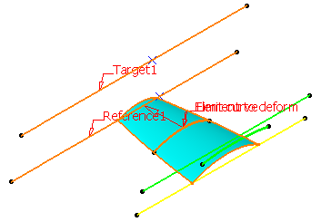
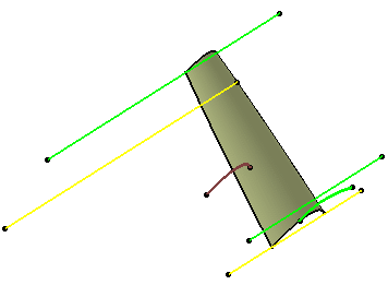
Successively select the first reference element and the first target element.
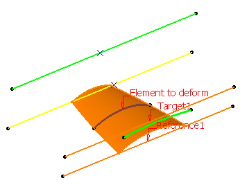
Click Preview to visualize the deformation.
It shows that:
- The deformation is applied to a group of points
- There is a constraints' mapping between the reference and the target curves.
You can visualize the mapping constraint by selecting a number in the dialog box.
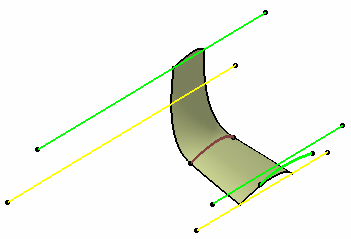
Click OK to create the deformed element.
The element (identified as Shape Morphing.xxx) is added to the specification tree.
You can apply a constraint on the target element with the associated support surface. The list displays the available continuity types depending on the reference/target elements you chose.
-
If you select a reference and a target element, the Point and the Tangent continuity are available. In case of Point continuity, the Support box is unavailable.
In case of Tangent continuity, select a support surface so that the continuity is kept. - If you select only reference elements, all continuities (Point, Tangent, and Curvature) are available. In the case of tangent or curvature continuity, you do not need to select a support surface as the surface to deform is taken into account.
- If you select the Type as Reference translation / Reference isometry / Reference similarity / Reference linear transformation, the None (G0), Rigid tangency and Rigid space continuities are available.
-
![]()
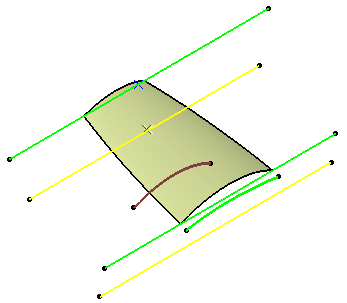
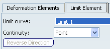
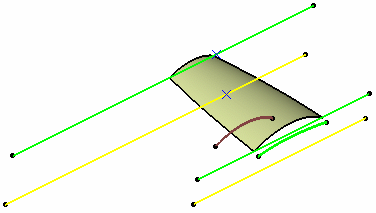
Define a Limit Element
You can define a limit curve to determine the area of the deformation and enable the other part of the element to remain frozen.
![]()
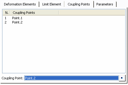
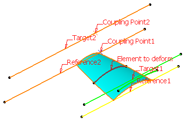
Couple Points
You can define coupling points to create desired deformation of the element.
- Use this tab to define coupling points in order to map reference
elements with target elements.
| Warning: The points must be located on reference and target curves. |
Important:
|
| Tip: Reference and target curves can be multi-cells. Joined, blended, or matched curves, for example, can be used as reference or target curves. |
![]()
Use the Parameters Capability
You can add parameters and create constraints to the deformed shapes.
- Use this tab to define the constraint propagation of the deformed surface to obtain the desired shape.
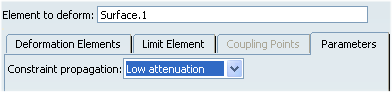
The different constraint propagation are:
- Low attenuation
- Medium attenuation
- Strong attenuation
- Very strong attenuation
Important: The constraint propagations Strong attenuation and Very strong attenuation cannot maintain the Reference linear transformation continuity.
![]()
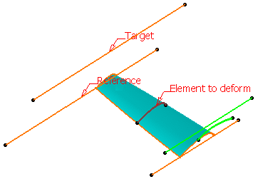
Deform the Surface with a Fixed Element
Sometimes, you need to create a deformed element in relation to another element. The shape morphing capability lets you fix an element that can be used by another one, thus allowing you to retain a connection between elements while deforming the initial element.
Click Shape Morphing
.The Shape Morphing Deformation Definition dialog box appears.
![]()
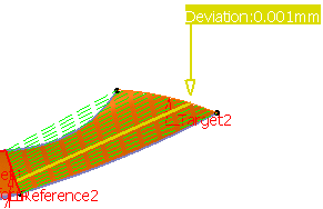
Use the Diagnosis Capability
The diagnosis capability lets you visualize the deviations in the 3D area when the result is not fully accurate.
The Warnings dialog box may also be displayed. Refer to Managing Warnings for further information.
Click Shape Morphing
.The Shape Morphing Deformation Definition dialog box appears.
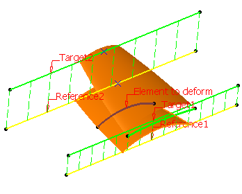
Select the reference and target elements as shown in the picture below:
Click Preview to visualize the deviations:
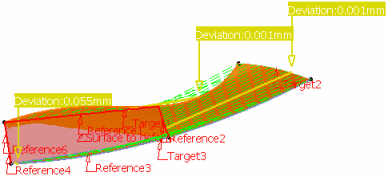
Select a line in the dialog box to display the corresponding mapping and deviation.
Here are the cases where warnings are displayed.
- When inputs are of bad quality:
- If the reference or target curves are not continuous.
- If the reference or target curves are not continuous in tangency or in curvature and the discontinuities are not coupled.
To solve the above warnings, we advise you to :
-
Use the Curve Smooth command to smooth the small discontinuities, then
-
Use the Coupling point tab to associate the tangency or curvature discontinuities between target and reference.
- When the reference curves intersect, there can be an
incompatibility between constraints:
- If the targets do not intersec.t
- If the targets intersect but the mapping between reference and targets do not associate the reference's intersection with the targets' intersection. In this case, we advise you to add coupling points.
- If the tangency constraint cannot be guaranteed.