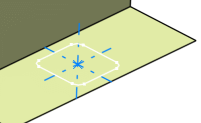
Click Hole Curve
 in the BiW Templates toolbar.
The Hole Curve Definition dialog box appears.
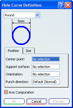
Various shapes can be created:
- round
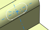
- slot (elongated hole)
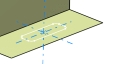
- rectangular
- square
The shape is defined on a plane and projected along a direction
on the surface. In that case, the nearest projection is used to
create the hole.
Select the shape in the drop-down list.
Click a point to be the Center Point in the
geometry or in the specification tree.
Select the Support surface.
Define the Orientation to align the
major axis along a direction.
Define the Punch direction.
Select the Axis Computation option to automatically create an axis and direction lines passing through the center of the hole curve.
The axis is created passing through the center of the hole curve along the punching direction. One of the direction lines is created along the input orientation direction, while the other direction line is created mutually perpendicular to the axis and the first direction line.
By default, this option is selected.
Click Preview.
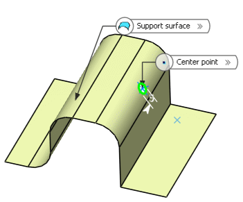
Define the shape dimensions.
To do so, either :
Click OK to create the hole curve.
The element (identified as Type Hole Curve.xxx) is
added to the specification tree.
Round hole curve
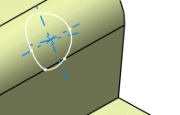
Slot hole curve
Rectangular hole curve
Square hole curve
