Working with a 3D Support | ||||||
|
| |||||
Click Work on Support 3D
 in the Tools toolbar.
The Work On Support 3D dialog box appears.
Part Design default configurations do not provide this icon in the standard toolbar. If you wish to access it, simply use the Customize capability to add this icon to the toolbar of your choice. Otherwise, select the item from the menu bar.
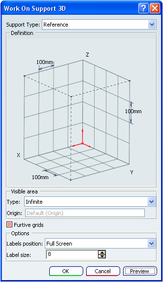
Important: - Each of three grid lines has one default primary spacing of 100mm for each direction. The three directions of the main axis system define the grids directions. When the local axis system is modified, all related features are updated.
- You can edit the spacing values by clicking on the spacing tag to edit and modify them. Note that you can modify these values at creation, not at edition, and that there can only be one value per grid.
- You can also modify the name of the labels of the main directions by clicking on the direction tag.
- Labels' directions and primary spacing are defined in Tools > Options > Shape > Generative Shape Design. Refer to the Customizing section for further information.
Select the Type of the visible area, that is the visualization range for each of the three grids:
- Infinite (default type): the visible area corresponds to the three infinite planes.
Note: If selected, the Furtive grids option is automatically selected and the Support Type and Origin fields are grayed out.
- Finite: an origin point that defines the intersection of the three grids should be selected (if not, the default origin of the reference or local axis system is taken into account).
You can define which area is to be visualized from the origin point for each of the three grids. To do so, select a position among the 8 possible positions (defined by double dots as shown in the picture above).
Once you have clicked Preview, the three limited grids appear along with manipulators to resize the visible area of the grids.
Note: If selected, the Furtive grids option is automatically cleared.
Important: In Infinite mode, there can be only one reference 3D work on support, whereas in Finite mode, multiple 3D working supports can be created for both Local and Reference support types.
- Infinite (default type): the visible area corresponds to the three infinite planes.
Optional: From the Grid sub-toolbar, click Grid Featurization Switch
 to create either featurized lines or featurized planes
on the grid lines. Featurized planes are created normal
to the current grid.
to create either featurized lines or featurized planes
on the grid lines. Featurized planes are created normal
to the current grid.Optional: From the Grid sub-toolbar, click Snap to point
 to snap the point being created onto the
nearest intersection point on the grid.
to snap the point being created onto the
nearest intersection point on the grid.
Click OK in the dialog box.
The elements (identified as Working support 3D.xxx) are added to the specification tree under the Working supports node.
The 2D working supports belonging to the 3D working supports feature are displayed in the specification tree and are aggregated under the 3D feature. Therefore, the visualization of the three grids can be individually controlled by the Hide/Show contextual command.
Warning: - The work on support must be parallel to one of the three planes to be visualized. As a consequence, the active 3D work on support may be seen independently in each view of the same document.
- There can only be one active 3D work on support at the same time.
Click Top View
 from the Quick View toolbar.
The active work on support is visualized and labels are displayed on each straight line.
Important:
|