A button  is available besides the Plane type to prevent an
automatic change of the type while selecting the geometry. Simply
click it so that the lock turns red is available besides the Plane type to prevent an
automatic change of the type while selecting the geometry. Simply
click it so that the lock turns red  .
For instance, if you choose the Offset From Plane type, you are
not able to select a line. May you want to select a line, choose
another type in the combo list. The status of this button is stored as the default value: therefore, if it is red and you launch the same command again or another command owning this button, the button will be red too. .
For instance, if you choose the Offset From Plane type, you are
not able to select a line. May you want to select a line, choose
another type in the combo list. The status of this button is stored as the default value: therefore, if it is red and you launch the same command again or another command owning this button, the button will be red too.
Create a Plane Offset From another Plane
You can create a plane parallel to a reference plane offset at a distance.
Click Plane
 . .
The Plane Definition dialog box appears.
In the Plane type list, select the Offset from plane plane type.
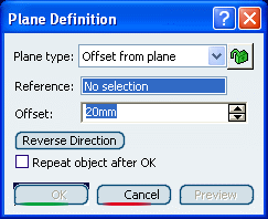
In the Reference box, select a plane and enter the value in the
Offset box.
A plane is displayed offset from the reference plane.
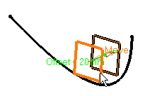
Click Reverse Direction tab to reverse the change
the offset direction, or click on the arrow in the geometry. Select the Repeat object after OK check box if you want to
create more offset planes.
In this case, the Object Repetition dialog box is displayed, and
you enter the number of instances to be created before clicking
OK.
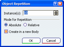
As many planes as indicated in the dialog box are created
(including the one you were currently creating), each separated from
the initial plane by a multiple of the Offset value.
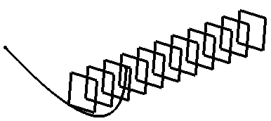
Click OK to create the plane.
The plane (identified as Plane.xxx) is added to the specification
tree.

Create a Plane Parallel to a Plane and through a Point
You can create a plane parallel to a reference plane through a point.
Click Plane
 . .
The Plane Definition dialog box appears.
In the Plane type list, select the Parallel through point plane type.
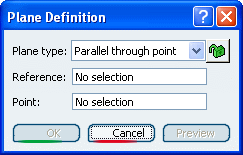
In the Reference box, select a plane. In the Point box, select a point.
A plane is displayed parallel to the reference plane and passing through
the selected point.
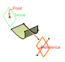
Click OK to create the plane. The plane (identified as Plane.xxx) is added to the specification
tree.

Create a plane Normal to another Plane
You can create a plane at an angle to a reference plane based on a rotation axis.
Click Plane
 . .
The Plane Definition dialog box appears.
In the Plane type list, select the Angle/Normal to plane plane type.
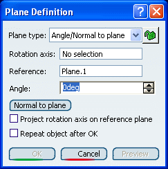
In the Reference box, select a plane. In the Rotation
axis box, select an axis or a line.
This axis can be any line or an implicit element, such as a
cylinder axis for example. To select the latter press and hold the
Shift key while moving the pointer over the element, then click it.
In the Angle box, enter the value.
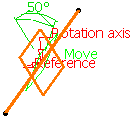
The plane is displayed such as its center
corresponds to the projection of the center of the reference plane on
the rotation axis. It is oriented at the specified angle to the
reference plane.
Select the Projection rotation axis on reference plane check box, if you want to project the rotation axis onto
the reference plane. If the reference plane is not parallel to the
rotation axis, the created plane is rotated around the axis to have the
appropriate angle with regard to reference plane. Select the Repeat object after OK check box if you want to
create more planes at an angle from the initial plane.
In this case, the Object Repetition dialog box is displayed, and
you enter the number of instances to be created before clicking
OK.

As many planes as indicated in the dialog box are created
(including the one you were currently creating), each separated from
the initial plane by a multiple of the Angle value.
Here we created five planes at an angle of 20 degrees.

Click OK to create the plane. The plane (identified as Plane.xxx) is added to the specification
tree.

Create a Plane Through Three Points
You can create a plane passing through three points.
Click Plane
 . .
The Plane Definition dialog box appears.
In the Plane type list, select the Through three points plane type.
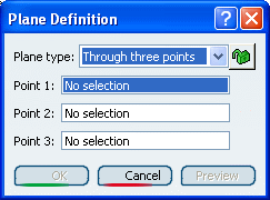
Select three points. A plane passing through the three
points is displayed. You can move it by dragging it to the desired
location.
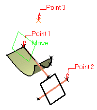
Click OK to create the plane. The plane (identified as Plane.xxx) is added to the specification
tree.

Create a Plane Through Two Lines
You can create a plane passing through two points.
Click Plane
 . .
The Plane Definition dialog box appears.
In the Plane type list, select the Through two lines plane type.
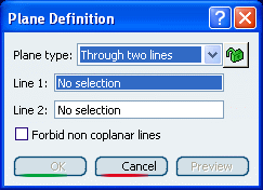
Select two lines.
The plane passing through the two line directions is displayed.
When these two lines are not coplanar, the vector of the second line
is moved to the first line location to define the plane's second
direction.
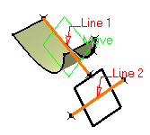
Select the Forbid non coplanar
lines check box to specify that both lines be in the same plane. Click OK to create the plane. The plane (identified as Plane.xxx) is added to the specification
tree.

Create a Plane Through a Point and a Line
You can create a plane passing through a point and a line.
Click Plane
 . .
The Plane Definition dialog box appears.
In the Plane type list, select the Through point and line plane type.
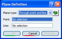
In the Point box, select a reference point. In the Line box, select the reference line.
A plane
passing through the point and the line is displayed.
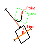
Click OK to create the plane. The plane (identified as Plane.xxx) is added to the specification
tree.

Create a Plane Through a Planar Curve
You can create a plane passing through a planar curve.
Click Plane
 . .
The Plane Definition dialog box appears.
In the Plane type list, select the Through planar curve plane type.
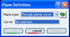
In the Curve box, select a planar curve.
A plane containing the
curve is displayed.
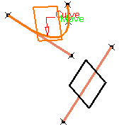
Click OK to create the plane. The plane (identified as Plane.xxx) is added to the specification
tree.

Create a Plane Normal to a Curve
You can create a plane normal to a curve at a specified points..
Click Plane
 . .
The Plane Definition dialog box appears.
In the Plane type list, select the Normal to curve plane type.
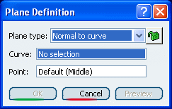
In the Curve box, select a reference curve. In the Point box, select a reference point. By default, the
curve's middle point is selected.
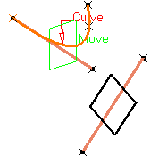
A plane is displayed normal to the curve with its origin at the
specified point. The normal is computed at the point on the curve
that is the nearest to the selected point.
Click OK to create the plane. The plane (identified as Plane.xxx) is added to the specification
tree.

Create a Plane Tangent to a Surface
You can create a plane tangent to a surface passing through a specified point.
Click Plane
 . .
The Plane Definition dialog box appears.
In the Plane type list, select the Tangent to surface plane type.
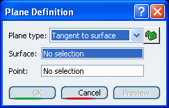
In the Surface box, select a reference surface.
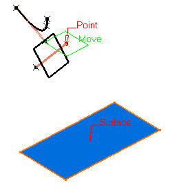
In the Point box, select a reference point. A plane is displayed tangent to the surface at the specified point.
Click OK to create the plane. The plane (identified as Plane.xxx) is added to the specification
tree.

Create a Plane Using an Equation
You can create a plane by defining the componenets of the equation of the plane.
Click Plane
 . .
The Plane Definition dialog box appears.
In the Plane type list, select the Equation plane type.
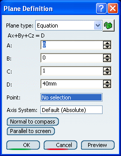
Enter the A, B, C,
D components of the Ax + By + Cz = D plane equation. Select a point to position the plane through this point,
you are able to modify A, B, and C
components, the D component becomes grayed.
When the command is launched at creation, the initial value in
the field is the
current local axis system. If no local axis system is current, the
field is set to Default.
Whenever you select a local axis system, A, B, C, and D values are
changed with respect to the selected axis system so that the location
of the plane is not changed. This is not the case with values
valuated by formulas: if you select an axis system, the defined
formula remains unchanged.
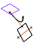
Click Normal to compass
to position the plane perpendicular to the compass direction.
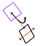
Click Parallel to screen to position the plane
parallel to the screen current view.
Click OK to create the plane. The plane (identified as Plane.xxx) is added to the specification
tree.

Create a Mean Plane Through Points
You can create a plane defined as the mean through three or more points.
Click Plane
 . .
The Plane Definition dialog box appears.
In the Plane type list, select the Mean through points plane type.
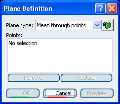
Select three or more points to display the mean plane
through these points.
It is possible to edit the plane by first selecting a point in
the dialog box list then choosing an option to either:
- Remove the selected point
- Replace the selected point by another point.
Click OK to create the plane.
The plane (identified as Plane.xxx) is added to the specification
tree.
|
![]() is available besides the Plane type to prevent an
automatic change of the type while selecting the geometry. Simply
click it so that the lock turns red
is available besides the Plane type to prevent an
automatic change of the type while selecting the geometry. Simply
click it so that the lock turns red ![]() .
For instance, if you choose the Offset From Plane type, you are
not able to select a line. May you want to select a line, choose
another type in the combo list. The status of this button is stored as the default value: therefore, if it is red and you launch the same command again or another command owning this button, the button will be red too.
.
For instance, if you choose the Offset From Plane type, you are
not able to select a line. May you want to select a line, choose
another type in the combo list. The status of this button is stored as the default value: therefore, if it is red and you launch the same command again or another command owning this button, the button will be red too.![]()
![]()
![]()
![]()


