A button  is available besides the Line type to prevent an
automatic change of the type while selecting the geometry. Click it so that the lock turns red is available besides the Line type to prevent an
automatic change of the type while selecting the geometry. Click it so that the lock turns red  .
For instance, if you choose the Point-Point type, you are
not able to select a line. If you want to select a line, choose
another type in the list.
The status of this button is stored as the default value: therefore, if it is red and you launch the same command again or another command owning this button, the button will be red too. .
For instance, if you choose the Point-Point type, you are
not able to select a line. If you want to select a line, choose
another type in the list.
The status of this button is stored as the default value: therefore, if it is red and you launch the same command again or another command owning this button, the button will be red too.
Create a Line Between Two Points
You can create a line between two selected points.
Click Line
 . .
The Line Definition dialog box appears.
In the Line type list, select the Point-Point line type.
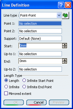
Select two points.
A line is displayed between the two points.
Proposed Start and
End points of the new line are shown.
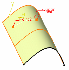
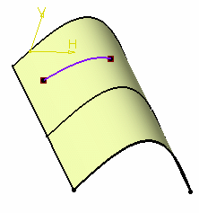
If needed, select a support surface.
In this case a geodesic line is created, i.e. going
from one point to the other according to the shortest distance along
the surface geometry (blue line in the illustration below).
If no surface is selected, the line is created between the two points
based on the shortest distance.
Specify the Start and End points of
the new line, that is the line endpoint location in relation to the
points initially selected.
These Start and End points are necessarily
beyond the selected points, meaning the line cannot be shorter than
the distance between the initial points.
Select the Mirrored extent check box to create a line
symmetrically in relation to the selected Start and End
points.
Click OK to create
the line.
The line (identified as Line.xxx) is added to the specification
tree.

Create a Line Using a Point and a Direction
You can create a line based on a reference point and a specified direction.
Click Line
 . .
The Line Definition dialog box appears.
In the Line type list, select the Point-Direction line type.
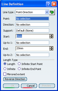
Select a reference Point and a Direction
line.
A vector parallel to the direction line is displayed at the
reference point.
Proposed Start and End points of the new line
are shown.
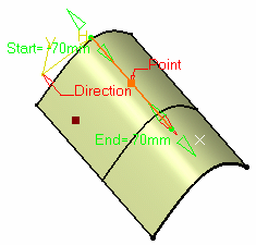
If needed, select a support surface.
In this case a geodesic
line is created, i.e. the
direction of the created line corresponds to the projection
of the given direction onto the support.
Specify the Start and End points of
the new line.
The corresponding line is displayed.
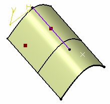
Click OK to create
the line.
The line (identified as Line.xxx) is added to the specification
tree.

Create a Line Normal to a Curve
You can create a line at an angle to a curve that passes through a point.
Click Line
 . .
The Line Definition dialog box appears.
In the Line type list, select the Angle/Normal to curve line type.
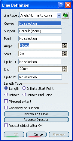
Select a reference Curve and a Support
surface containing that curve.
Select a Point on the curve. Enter an Angle value.
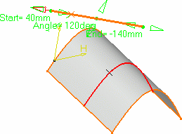
A line is displayed at the given angle with respect to the
tangent to the reference curve at the selected point. These elements
are displayed in the plane tangent to the surface at the selected
point.
You can click on the Normal to Curve
button to specify an angle of 90 degrees.
Proposed Start and End points of the line are
shown.
Specify the Start and End points of
the new line.
The corresponding line is displayed.
Select the Repeat object after OK check box if you want to
create more lines with the same definition as the currently created
line.
In this case, the Object Repetition dialog box appears, and you key in the number of instances to be created
before clicking OK.
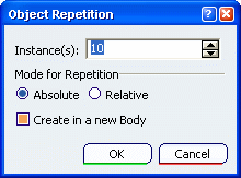
As many lines as indicated in the dialog box are
created, each separated from the initial line by a multiple of the
angle value.
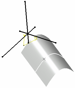
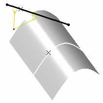
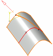
You can select the Geometry on Support check box if you
want to create a geodesic line onto a support surface.
The figure below illustrates this case. Geometry on support option cleared
Geometry on support option selected
Click OK to create
the line.
The line (identified as Line.xxx) is added to the specification
tree.

Create a Line tangent to a Curve
You can create a line tangent to a single curve, a point and a curve or two curves.
Click Line
 . .
The Line Definition dialog box appears.
In the Line type list, select the Tangent to curve line type.
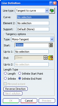
Select a reference Curve and a point
or another Curve to define the tangency.
-
if a point is selected (mono-tangent mode): a vector tangent to
the curve is displayed at the selected point.
-
If a second curve is selected (or a point in bi-tangent mode),
you need to select a support plane. The line will be tangent to
both curves.
Line tangent to curve at a given point
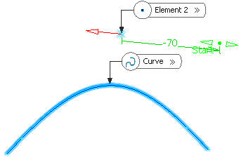
When several solutions are possible, you can choose
one (here displayed in green) directly in the geometry, or using the
Next Solution button:
Line tangent to two curves
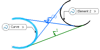
Optional: Specify the Start point to
define the new line.
Click OK to create
the line.
The line (identified as Line.xxx) is added to the specification
tree.

Create a Line Normal to a Surface
You can create a line normal to a surface at a selected point.
Click Line
 . .
The Line Definition dialog box appears.
In the Line type list, select the Normal to surface line type.
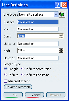
Select a reference Surface and a Point.
A vector normal to the surface is displayed at the reference
point.
Proposed Start and End points of the new line
are shown.
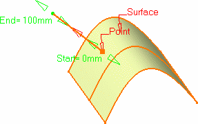
If the point does not lie on the support
surface, the minimum distance between the point and the surface is
computed, and the vector normal to the surface is displayed at the
resulted reference point.
Optional: Specify Start and End points to
define the new line.
Click OK to create
the line.
The line (identified as Line.xxx) is added to the specification
tree.

Create a Line at the Bisection of Two Lines
You can create a line that bisects the angle between two lines into equal parts.
Click Line
 . .
The Line Definition dialog box appears.
In the Line type list, select the Bisecting line type.
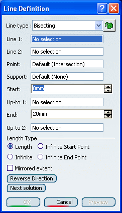
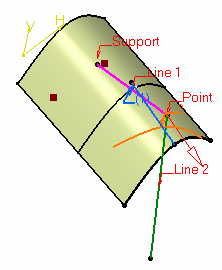
Select two lines. Their bisecting line is the line
splitting in two equals parts the angle between these two lines. Select a point as the starting point for the line. By
default it is the intersection of the bisecting line and the first
selected line. Select the support surface onto which the bisecting line
is to be projected, if needed. Specify the line's length by defining Start
and End values (these values are based onto the default start
and end points of the line).
The corresponding bisecting line, is displayed.
You can choose between two solutions, using the Next
Solution button, or directly clicking the numbered arrows in the
geometry.
Click OK to create
the line.
The line (identified as Line.xxx) is added to the specification
tree.

Create a Line Up to an Element
You can create a line up to a point,
a curve, or a surface.
Up to a point
You can create a line up to a point.
Up to a curve
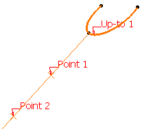
You can create a line up to
a curve.
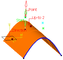
Up to a surface
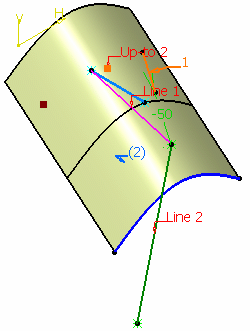
You can create a line up to a surface.

Create a Series of Lines Using the Last Point
You can create a series of lines by automatically reelecting the last
selected point.
Double-click Line
 . . Create the first point.
The Reselect Second Point at next start check box appears
in the Line Definition dialog box.
Select it to be able to later reuse the second point. Create the second point.
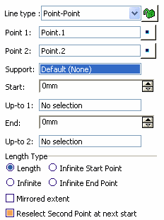
Click OK to create the first line.
The Line Definition dialog box opens again with the first
point initialized with the second point of the first line.
Click OK to create the second line.
|
![]() is available besides the Line type to prevent an
automatic change of the type while selecting the geometry. Click it so that the lock turns red
is available besides the Line type to prevent an
automatic change of the type while selecting the geometry. Click it so that the lock turns red ![]() .
For instance, if you choose the Point-Point type, you are
not able to select a line. If you want to select a line, choose
another type in the list.
The status of this button is stored as the default value: therefore, if it is red and you launch the same command again or another command owning this button, the button will be red too.
.
For instance, if you choose the Point-Point type, you are
not able to select a line. If you want to select a line, choose
another type in the list.
The status of this button is stored as the default value: therefore, if it is red and you launch the same command again or another command owning this button, the button will be red too.![]()
![]()
![]()
![]()
![]()
