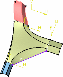
Click Junction
 in the BiW Templates toolbar.
The Junction Surface definition dialog box appears.
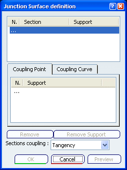
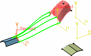
Select two sections.
These can be surface boundaries or contour lying on surfaces.
Coupling curves on which the junction surface will be based are
displayed between the two sections.
Select another section.
New coupling curves are now displayed.
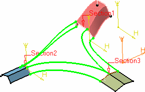
If the sections do not present the same number of vertices, the
system automatically links the coupling curves to the sections
retaining the maximum number of points.
In our example, two sections present four vertices whereas the
last one presents only three. The system found a solution by linking
two curves to the same vertex on the last section.
Use the Sections coupling combo list to specify if the
coupling lines are to connect sections on their tangency
discontinuity points (Tangency option) or on their
tangency discontinuity and curvature discontinuity points (Curvature
option).
Click within the Coupling
Point area then select a point on the section on which you wish to
redefine a new passing point for the coupling curve.
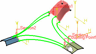
Click Preview to preview the junction surface:
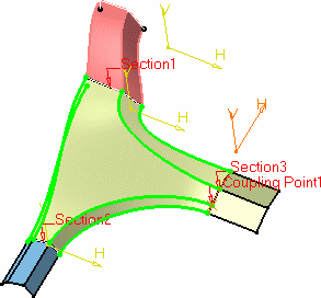
By default the coupling curves and the junction surface are
tangent to the contour plane's normal.
Select a section from the list and click the surface on
which it lies to add it as a support surface to the section, and
therefore define a tangency constraint.
The coupling curves are modified so as to be tangent
to the selected surface.
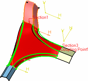
You can also specify a user-defined coupling
curve rather than an automatic one, by
clicking the Coupling Curve tab, then selecting another
curve connecting two sections of the junction.
This new coupling curve either replaces an automatic
one, or results in a new computation of automatic coupling curves.
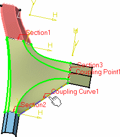
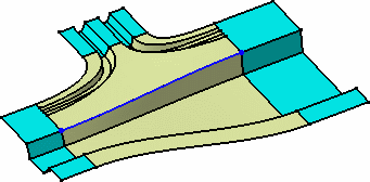
Indeed, in the following example, the user-defined
coupling curve lies across the automatic ones. These are therefore
recomputed to comply with the new constraint:
Using automatic coupling curves only
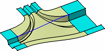
Recomputed automatic coupling curves when using a user-defined
coupling curve (blue curve)
Click OK to create the junction surface.
The element (identified as Junction.xxx) is added to the
specification tree.
