Thread Turning | |||||
|
| ||||
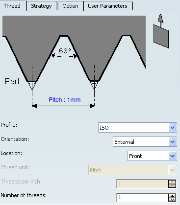
Strategy: Thread Parameters
- Tool Axis
- SeeDefining the Tool Axis
- Profile
- Specifies a thread profile.
You can specify:
- ISO
- Trapezoidal
- UNC
- Gas
- Other: The Other allows defining a specific thread profile.
- Orientation
- Specifies the type of machining according to the
location of the area to machine on the part.
You can specify:
- External
- Internal
- Location
- Specifies location.
You can specify:
- Front: The profile is machined toward the head stock.
- Back: The profile is machined from the head stock.
- Thread unit
- Specifies the thread unit.
This option is activated when the Profile is specified as Other. Thread unit is automatically set to Threads per Inch for the ISO, Trapezoidal UNC, and Gas types.
- Threads per Inch
- Specifies the threads per Inch.
This option is activated when the Profile is set to Other and Thread unit is set to Threads per Inch.
- Number of Threads
- When value is specified greater than 1, then this value allows you to specify whether a multi-start
thread is to be machined.
This option is activated when the Profile is set to Other and Thread unit is set to Threads per Inch.
- Nominal Diameter
- This value must be given when Thread type is Internal and Profile is Other.
- Thread Pitch
- This value must be given when the Thread type is set to Pitch or the Profile is ISO or Trapezoidal.
- Thread Depth
- This value must be given when the Thread profile is Other
![]()
Strategy Parameters
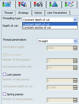
- Threading Type
- Choose the desired threading type.
You can specify:
- Constant depth of cut
- Constant section of cut
- Depth of cut
- Specifies the depth of cut.
This option is available only when Threading Type is set to Constant depth of cut.
- Number of passes
- Specifies the number of passes.
This option is available only when Threading Type is set to Constant section of cut. When the number of passes is defined, the section of cut value is automatically set.
- Thread Penetration
- Specifies thread penetration.
You can specify:
- Straight
- Oblique: Also specifies the Penetration angle.
- Alternate: Also specifies the Penetration angle.
This option is available only when Threading Type is set to Constant depth of cut
- First Passes
- Select First passes
check box to manage penetration on first passes.
This option is available when Threading type is set to Constant section of cut. When activated, you must specify values for:
- Number of first passes
- First section rate.
- Last Passes
- Select Last passes
check box to manage penetration on the last passes.
This option is available when Threading type is set to Constant section of cut. When activated, you must specify:
- Number of last passes
- Depth of cut for last passes.
- Spring Passes
- Select Spring passes
check box to manage penetration on the spring passes.
This option is available when Threading type is set to Constant section of cut. When activated, you must specify Number of spring passes
![]()
Strategy: Option Parameters
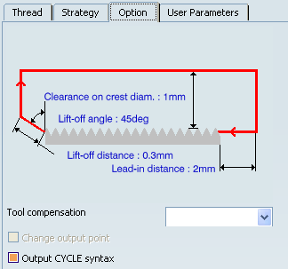
- Clearance on crest diameter
- Specifies the clearance on crest diameter.
- Lead-in Distance
- Specifies the Lead-in Distance with respect to the cutting direction.
The tool is in RAPID mode before this distance.
- Lift-off Distance and Lift-off Angle
- Specifies the Lift-off Distance and Lift-off Angle to define the lift-off vector at the end of each pass with
respect to the cutting direction.
The figure below shows the effect of a positive lift-off angle for external machining.
- Tool Compensation
- Select
a tool compensation number corresponding to the desired tool
output point.
The usable compensation numbers are defined on the tool assembly linked to the machining operation.
 By default,
the output point corresponding to type P9 can be used, if you do not select a tool compensation
number.
By default,
the output point corresponding to type P9 can be used, if you do not select a tool compensation
number. - Change Output Point
- Select the Change Output Point check box to automatically manage the change of output point.
Change Output Point option is available for Trapezoidal or Other profile.
- Output Cycle Syntaxes
- Select the Output
CYCLE syntax check box to generate CYCLE statements.
Also select the Output CYCLE syntax check box in the NC Output Generation dialog box, to generate CYCLE statements. . Otherwise, GOTO statements can be generated.
The parameters available for PP word syntaxes for this type of operation are described in the PP Tables and PP Word Syntaxes section of the NC Manufacturing Infrastructure User's Guide.
Editing CYCLE Syntaxes
The Edit
Cycle  command in the Thread Turning dialog box allows you to:
- display the unresolved syntax of the NC Instruction of the operation. This is the syntax as specified in the PP table referenced by the current Part Operation.
- display and, if needed, edit the syntax that is resolved either by geometric selection and user entries.
The Cycle Syntax Edition dialog box is displayed when you click the Edit Cycle command.
You can access all the CYCLE syntaxes contained in the current PP table
by clicking PP Instruction
![]() .
You can then select the desired syntax to be used by means of the procedure
described in the
Inserting PP Instructions section.
.
You can then select the desired syntax to be used by means of the procedure
described in the
Inserting PP Instructions section.

If your PP table is customized with the following statement for Thread Turning operations:
CYCLE/THREAD,%MFG_THREAD_PITCH
then a typical NC data output is as follows:
CYCLE/THREAD, 10.000000
The parameters available for PP word syntaxes for this type of operation are described in the PP Tables and PP Word Syntaxes section of the NC Manufacturing Infrastructure User's Guide.
![]()
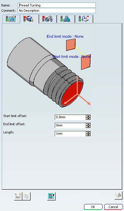
Geometry
- Part profile
- Part profile is required. It can be specified by selecting edges either directly or after selecting the By Curve contextual command.
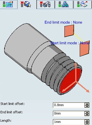
- Limit Mode
- Start Limit Mode: This option allows you to specify a point, line, curve, or face as the start element of the profile to be machined. If a face is specified, the start element is the intersection of the face and the working plane. The position of the start of machining is also defined with respect to this element. In / On / Out allows you to specify the Go-Go type positioning of the tool with respect to the start element. The On option is always used for a point type end element. If needed, the profile may be extrapolated to the start element.
- End Limit Mode: This option allows you to specify a point, line, curve, or face as the end element of the profile to be machined. If a face is specified, the end element is the intersection of the face and the working plane. The position of the end of machining is also defined with respect to this element. In / On / Out allows you to specify the Go-Go type positioning of the tool with respect to the end element. The On option is always used for a point type end element. If needed, the profile may be extrapolated to the end element
Note: To avoid collisions of tool with limit geometry or unwanted machining beyond limits with In option, either define limits with suitable offset value or include limit geometry as part element (this is better wherever applicable) and avoid limit definition.
Relimiting the Area to Machine by means of Limit Mode:
- If you specify a point, it is projected onto the part profile. A line through the projected point parallel to the radial axis delimits the area to machine.
- If you specify a line, its intersection with the part profile is calculated (if necessary, the line is extrapolated). A line through the intersection point parallel to the radial axis delimits the area to machine.
- If you specify a curve, its intersection with the part profile is calculated (if necessary, the curve is extrapolated using the tangent at the curve extremity). A line through the intersection point parallel to the radial axis delimits the area to machine.
- Start Limit offset
- Specifies the distance with respect to the start element (only if start element is a line, curve or face, and when In or Out is set for start element positioning).
- End Limit Offset
- Specifies the distance with respect to the end element (only if end element is a line, curve or face, and when In or Out is set for end element positioning).
- Length
- This value must be given when the In / On / Out is set for Start Limit offset and None is set for End Limit offset, and vice versa.
![]()
Tools
The Internal  and External
  threading insert-holders with thread inserts
  may be used.
See Specifying a Tool Element in a Machining Operation and Creating or Editing a Probing, a Milling, or a Drilling Tool.
![]()
Feedrates and Spindle Speed Parameters
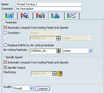
- Feedrate: Automatic compute from tooling Feeds and Speeds
- This check box allow a Machining Operation feeds and speeds values to be updated automatically when the tool's feeds and speeds values are modified.
- Transition
- You can locally set the feedrate for a transition path to a Machining Operation B from a Machining Operation A or from a tool change activity. This is done by selecting the Transition check box in the Machining Operation dialog box for Machining Operation B.
- Replace RAPID by Air cutting feedrate
- Select this check box to replace RAPID feedrate in tool trajectories (except
in macros) by Air cutting feedrate.
The changes in unit of Air cutting feed-rate, are also reflected in APT file output. Calculated cycle time in Properties dialog box of Machining Operation also get changed. There are changes in total time and machining time on Tool Path Replay dialog box.
Note:
The feedrates and Air cutting feedrate can be defined in linear (feed per minute) or angular (feed per revolution) units.
- Angular: feedrate in revolutions per minute and unit is set to mm_turn.
- Linear: feedrate in feed per minute and unit is set to mm_mn.
- Spindle Speed: Automatic compute from tooling Feeds and Speeds
This check box allow a Machining Operation feeds and speeds values to be updated automatically when the tool's feeds and speeds values are modified.
If the Feedrate Automatic compute check box is selected and the Spindle Speed: Automatic compute from tooling Feeds and Speeds check box is not selected, then only the feedrate values can be computed. If both are not selected then automatic updating is not done.
When you modify a tool's feeds and speeds, all existing Machining Operations with the Automatic compute checkboxes selected that use this tool (or an assembly using this tool) can be recomputed.
- Spindle output
- This check box manage output
of the SPINDL instruction in the generated NC data file. The instruction is generated, if the check box is selected. Otherwise,
it is not generated
Note:
The spindle speed can be defined in linear (length per minute) or angular (length per revolution) units.
- Angular: length in revolutions per minute and unit is set to mm_turn.
- Linear: length in feed per minute and unit is set to mm_mn.
- Quality
- The feeds and speeds values are computed according to the Quality setting on the Machining Operation.
- Compute
- Feeds and speeds of the operation can be updated according to tooling feeds and speeds by clicking the Compute button.
Feeds and speeds of the Machining Operation can be updated automatically according to tooling data and the rough or finish quality of the Machining Operation. See About Feeds and Speeds.
![]()
Macro Parameters
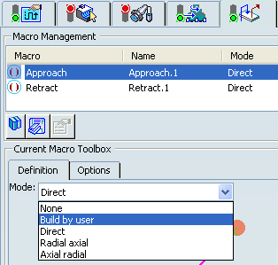
The selected macro type (Approach or Retract) defines the tool motion before
or after machining:
- Approach: to approach the Machining Operation start point.
- Retract: to retract from the Machining Operation end point.
The proposed macro mode are:
- None
- Build by user
- Direct
- Radial-axial
- Axial-radial
See Defining Macros.