Specifying a Tool Element in a Machining Operation | ||||||||
|
| |||||||
Create or double-click an existing Machining Operation and go to the Tools tab.
Note: When you create a Machining Operation:
- the Tools tab is empty if the Machining Operation is the first in the Activities Process Tree, or if the tool found in the previous Machining Operation or Tool Change is not compatible with the current Machining Operation.
- the Tools tab is populated with the tool of the previous Machining Operation or Tool Change, when possible.
The methods to select a tool or a tool assembly are the same, as described below.
Note: Lathe Machining operations require that you select an assembly. See Creating or Editing a Probing, a Milling, or a Drilling Tool.
To select a tool or a tool assembly from the Machining Cell:
This is equivalent to the contextual menu item Assign Tool from file in the Activities Process Tree. Using the Activities Process Tree.
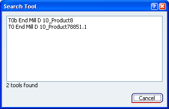
- Click ...
All the tools or tools assemblies present in the Machining Cell, and not yet used in the current Machining Operation, are listed in the dialog box that appears.
- Click ...
To list and import a tool or a tool assembly from a file or a catalog:
- Click
 .
. - Proceed as explained in List and Import Tools or List and Import Tool Assemblies.
Note: The csv file is used only for Import List Tool
 command. The csv files are not available while editing machining operations because they create tools and catalogs do not create but import tools. It is not possible to create a tool while editing an operation, so csv files are not available.
- Only the icons of the tools or tool assemblies compatible with the current Machining Operation are displayed.
- To list all tools available on the machine irrespective of the type, click All Tools
 .
.
- Click
To query a tool or a tool assembly from the data base or from the session:
This is equivalent to the contextual menu item Assign Tool from data base in the Activities Process Tree. Using the Activities Process Tree.
- Click
 .
. - Proceed as explained in Using the PLM Chooser
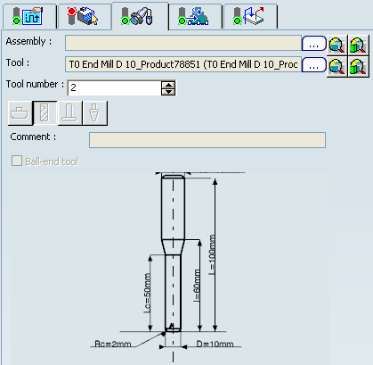
Whatever the method chosen:
- the name of the tool or tool assembly is displayed,
- the icon representing its type is pressed, but is not editable,
- when relevant, the Ball-end tool check box is selected, but is not editable,
- a representation of the tool or tool assembly with their parameters is displayed, but is not editable.
- Click
Click OK to validate and exit the Machining Operation dialog box.
The Activities Process Tree is updated with the Resources name of the tool or tool assembly, as shown below

