About Feeds and Speeds | |||||
|
| ||||
Cutting Conditions
Cutting conditions (feed/tooth and cutting speed) can be included in a tools catalog. This data is converted into machining feedrate and spindle speed parameters to be used in Machining Operations by means of Formulas.
For an example of such a tools catalog, see FeedsAndSpeeds.xls file delivered in the .../startup/Manufacturing/Samples folder.
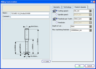
Cutting conditions are also available in the Feeds and Speeds tab of the Tool Definition dialog box.
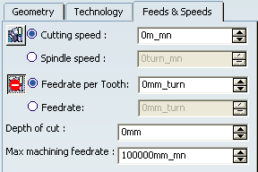
In the Feeds and Speeds tab of a Machining Operation dialog box, the Quality (Rough or Finish) of the Machining Operation and the tool data are taken into account for computing feeds and speeds.
The units associated to each attribute are set using the tab.
- For cutting speed, you can to choose the industry standard unit you are accustomed to: m/mn or ft/mn. Cutting speed is a linear value.
- For Spindle speed, the unit is turn/mn. Spindle speed is an angular value.
- Cutting speed and spindle speed are related as follows (when tool diameter units are in mm):
spindle speed = cutting speed*1000/(Pi*tool diameter)
- The Feedrate attribute represents the global feedrate of the tool. If you modify the global Feedrate, the Feedrate per tooth is updated according to the Formula:
feedrate per tooth = global feedrate/number of teeth
Note: the Feedrate per tooth cannot be edited directly in the Feeds & Speeds tab.
The following cutting conditions data are supported: cutting speed (Vc), feedrate/tooth (Sz), and depth of cut.
Cutting conditions for drilling tools:
 	MFG_VC: cutting speed in mm/mn
 	MFG_SZ: feedrate/tooth in mm/rev
 	MFG_PP: Depth of cut.
Roughing and Finishing cutting conditions for milling tools:
 	MFG_VC_FINISH: finishing cutting speed in mm/mn
 	MFG_SZ_FINISH: finishing feedrate/tooth in mm/rev
 	MFG_VC_ROUGH: roughing cutting speed in mm/mn
 	MFG_SZ_ROUGH: roughing feedrate/tooth in mm/rev.
Roughing and Finishing cutting conditions for lathe inserts:
 	MFG_VC_FINISH: finishing cutting speed in mm/mn
 	MFG_SZ_FINISH: finishing feedrate/tooth in mm/rev
 	MFG_SZ_AA_FINISH: axial depth of cut for finishing
 	MFG_SZ_AR_FINISH: axial depth of cut for finishing
 	MFG_VC_ROUGH: roughing cutting speed in mm/mn
 	MFG_SZ_ROUGH: roughing feedrate/tooth in mm/rev
 	MFG_SZ_AA_ROUGH: axial depth of cut for roughing
 	MFG_SZ_AR_ROUGH: axial depth of cut for roughing.
Note: For Machining Operations and associated tools handling finish or rough parameters, the finishing rotation speed can be a Finishing cutting speed or a Finishing spindle speed and the roughing rotation speed can be a Roughing cutting speed or a Roughing spindle speed.
When a tool is selected for a Machining Operation, the spindle speed (N) and machining feedrate (Vf) are computed using the following Formula:
N (rev/mn) = Vc / (D * PI)
where:
- D = tool diameter for milling/drilling in mm
- Vc = cutting speed of the tool.
For turning operations, N is automatically set in mm/min with the value of the insert cutting speed.
Vf (mm/rev) = Sz * N * Z
where:
- Sz = feedrate/tooth on the tool
- N = spindle speed in rev/min
- Z = number of teeth on the tool: (MFG_NB_OF_FLUTES) or 1 for a lathe insert.
Finishing data is used if the Machining Operation is finishing type (for example, Lathe Profile Finishing) or if it includes a finishing feedrate.
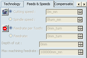
If the tool data is set to
0 (that is, if there are no specified values in the catalog),
the spindle speed N and machining feedrate Vf are not computed
on the Machining Operation. In such cases:
![]()
Access to Feeds and Speeds Parameters
Feeds and Speeds parameters can be accessed from several locations.
You can access Feeds and Speeds parameters from:
- the tool definition dialog box, when you click more:
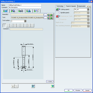
- the Machining Operation dialog box
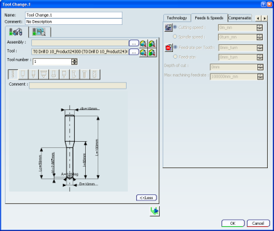
- or the Tool Change dialog box:
The values defined in the tool definition dialog box apply to the Machining Operations or Tool Changes that use the tool.
If access to the speeds and feedrates values is allowed, those values can be modified in the Machining Operations or Tool Changes, and then apply to all the Machining Operations or Tool Changes using this tool.
Note:
Access to the speeds and feedrates values is controlled by the administrator, from the tool definition dialog box, by switching the access icons from On  to Off
  and vice-versa:
- In this example, in the tool definition dialog box:
access is allowed to the speeds, but not to the feedrates. - in the the Machining Operations or Tool Changes dialog boxes:
- If you click the first icon , it turns to
 and lets you access the speeds value (you have to select the one you need to modify)
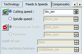
- while the second one is not clickable and prevents access to the feedrate value.
- If you click the first icon
This feature is useful for all Turning/Milling/Drilling tools.
![]()
Update of Feeds and Speeds on Machining Operation
You can update feeds and speeds values of the Machining Operation which are not automatically updated.
Machining Operation without Tool
As soon as a tool is assigned to a Machining Operation, the Machining Operation is updated with the tool feeds and speeds values.
Machining Operation with a Tool
When you modify a feedrate or spindle speed value in the tool definition dialog box, the feeds and speeds values of the Machining Operation need to be updated.
Feeds and speeds of the Machining Operation can be updated from the tool definition feeds and speeds:
- When you select a new tool,
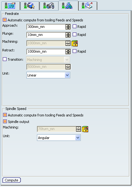
- When the Automatic compute from tooling Feeds and Speeds check boxes in Feedrate and Spindle Speed in the Feeds and Speeds tab of the Machining Operation are selected.
Note:
- The default values in the Machining Operations of these two check boxes can be set in .
- When these check boxes are selected, the update is performed automatically when the feeds and speeds values are modified in the tool definition dialog box.
- These two check boxes work separately.
- They can be selected separately and apply only to their respective area.
- When the feeds and speeds values are modified in the tool definition dialog box, all the existing Machining Operations where those check boxes are selected, and that use that tool (or an assembly using this tool) are re-computed.
- When you click Compute in
the Feeds and Speeds tab of the Machining Operation.
Note:
- Compute forces the update when the Automatic compute from tooling Feeds and Speeds check boxes are not selected.
- The computation of the feeds
and speeds of the Machining Operation depends on the Quality
setting:

- Rough: rough values of the tool are taken into account
- Finish: finish values of the tool are taken into account
- Either: no computation can be done for the operation feeds and speeds.
![]()
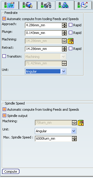
Maximum Spindle Speed
You can set a maximum spindle speed value for all turning and axial Machining Operations, and modify it in the Machining Operations to suit the cutting conditions.
You can access this parameter from:
- the Generic Machine dialog box, in the Mill-Turn Machine tab:
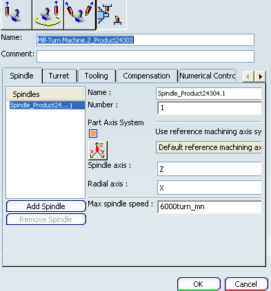
 By default,
Max spindle speed is set to 6000turn_mn. The minimum value is 1. The unit is always angular.
By default,
Max spindle speed is set to 6000turn_mn. The minimum value is 1. The unit is always angular. - the turning or axial Machining Operation dialog box:
The value of Max. Spindle Speed in the Machining Operation is editable, but can not exceed that of the machine (a message error is displayed if such is the case).
By default,
the value of Max. Spindle Speed in the Machining Operation is that defined in the machine. - from the Activities Process Tree, provided the Automatic compute from tooling Feeds and Speeds check boxes are not selected in the Machining Operation dialog box.
Note: Editing in the Activities Process Tree reverts to editing in the Machining Operation dialog box.
The maximum spindle speed value serves as output in the APT file at the beginning of theMachining Operation with the command name NC_SPINDLE_MAXSPEED and syntax MAXSPNDL/%MFG_MAX_SPNDL_SPEED, & MFG_MAX_SPNDL_UNIT.
Example:
*START_NC_COMMAND NC_SPINDLE_MAXSPEED
MAXSPNDL/%MFG_MAX_SPNDL_SPEED, & MFG_MAX_SPNDL_UNIT, &
MFG_SPNDL_WAY*END
![]()
Feeds and Speeds Change and Toolpath Computation
Depending on the type of Machining Operation and feedrate, when you modify a feedrate or spindle speed, the toolpath is not broken and is updated with the new value of feedrate or spindle speed, without having to recompute the tool path.
Note:
However, the tool path is broken when you modify:
- a local feedrate,
- a plunge, approach or retract feedrate in an axial Machining Operation,
- feedrate reduction in corners,
- feedrates defined in a turning Machining Operation.
In these cases, you need to recompute the toolpath.