In the
Strategy tab
of the operation, or in the machining feature dialog box, click the tool axis symbol:

You can also right-click the symbol
and choose Select.
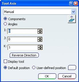
The Tool Axis dialog box is displayed.

Select one definition mode.

- Manual:
 sets the tool axis perpendicular
to the screen view, sets the tool axis perpendicular
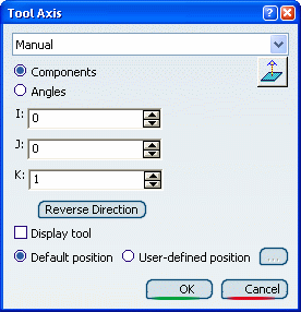
to the screen view,- Components
lets you define the tool axis orientation
by means of I, J, and K components.

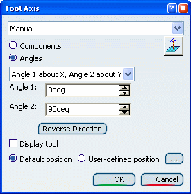
- Angles lets you
define the orientation by an
angular rotation with respect to
the X and Y, Z and X; or Y and Z
axes.


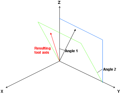
- Angle 1 about X, Angle 2 about Y: The tool axis is rotated an Angle 1 about the x-axis, then
rotated an Angle 2 about the y-axis.
- Angle 1 about Z, Angle 2 about X: The tool axis is rotated an Angle 1 about the
z-axis, then rotated an Angle 2 about the x-axis.
- Angle 1 about Y, Angle 2 about Z: The tool axis is rotated an Angle 1 about the y-axis, then
rotated an Angle 2 about the z-axis.
- Selection:
- select a line or linear
edge: the tool axis has the
same orientation as that element,
- or select a planar element:
the tool axis is normal to
that element.
- Points in the
View: select two points
in the authoring window to define the tool axis orientation.
- Feature defined: select a machining feature
in the authoring window, the axis of that feature becomes the tool axis.
The tool axis is visualized by means
of an arrow. Click Reverse Direction to invert the direction. When available, you can also choose to display the tool
at the Default position or at a User-defined
position. For a user-defined position, click the
[...] button and select the desired position in the
authoring window. Click OK to validate and exit the dialog box.
|