Defining Macros on Turning Operations | |||||
|
| ||||
Double-click Longitudinal Rough Turning operation in the Manufacturing Program.
Select the Macros tab
 .
.See Macros
The initial status of all the Macros in the Macro Management list is Inactive.
Right-click the Approach Macros line and click Activate in the context menu to activate the Macros.
- Select the
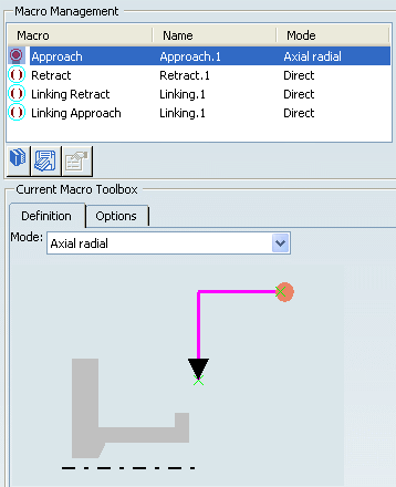
Axial radial mode
in the Current Macro Toolbox.
A sensitive icon representing the paths of the approach Macros appears.

- Select the point symbol in the sensitive icon then select
a point in the 3D window.
The radial and axial paths of the Macrosare calculated from the selected point to the start point of the operation.
- Select the
Axial radial mode
in the Current Macro Toolbox.
Click Tool Path Replay
 to check the axial approach.
 The status of the Macros becomes Up to date.
Right-click the Retract Macros line and click Activate in the contextual menu to activate the Macros.
- Select the
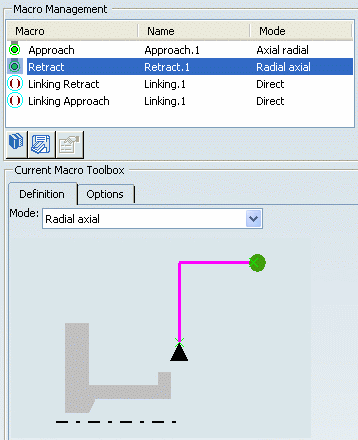
Radial axial mode
in the Current Macro Toolbox.
A sensitive icon representing the paths of the approach Macros appears.
- Select the point symbol in the sensitive icon then select
a point in the authoring window.
The axial and radial paths of the macro are calculated from the end point of the Machining Operation to the selected point.
- Click Tool Path Replay
 to check the axial retract.
 The status of the macro becomes Up to date.

- Select the
Radial axial mode
in the Current Macro Toolbox.
Select the Different colors mode
 in the Tool Path Replay, in order to visualize feedrate changes.
 The tool path is displayed with the following default colors:
- Yellow: Approach or lead-in feedrate
- Green: Machining feedrate
- Blue: Retract feedrate
- Red: Rapid or lift-off feedrate
- White: User-defined feedrate
Note: Transition paths are represented by dashed white lines.
Define the Linking Approach and Linking Retract macros in the same way as discussed above.
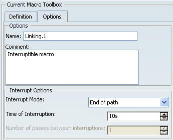
Define interrupt conditions for the Linking Macros in the Options tab of the Current Macro Toolbox, if required.
- Change Name, if required.
- Specify Comment, if required.
- Select Interrupt Modes for Linking macros.
Note: Linking macros, which are available for Rough, Groove, Recess, Ramp Rough, and Ramp Recess Turning operations, can be interrupted.
- No: Macros is not interrupted.
- Start of path: Interrupt macro at the start of the path where the specified time is reached.
- End of path: Interrupt Macros at the end of the path where the specified time is reached.
- On time: Interrupt Macros as soon as the specified time is reached.
- Number of paths: Interrupt macro at the end of the number of specified paths.
- By levels: Available for Groove Turning operations only, interrupt macro at the end of the number of specified levels. The specified time may correspond to the expected lifetime of the insert. This allows you to interrupt an operation in order to change a worn insert. This is useful when machining very hard materials.

Click OK to accept the modifications made to the Machining Operation.
The Machining Operation is updated with the specified macros.