Creating or Editing a Probing, a Milling, or a Drilling Tool

You can create tools using the Tool Builder toolbar. Once created, they are editable from the Machining Cell.

This task shows you how to:

Related Topics
About Representation Management
Taking Maximum Wear Cutting Condition into Account
Machining Resources
Working with Generic Machine Editor

Create a Probing, a Milling or a Drilling Tool

You can create a probing, a milling or a drilling tool from the Tool Builder toolbar.

  1. From any product:

    1. Select Start > Machining > Machine Programming.

      A PPR context with an empty Machining Cell is created. An empty Activities Process Tree opens automatically.

    2. Create a generic machine or assign a machine from the database.

      As soon as a machine is assigned to the Machining Cell, a Part Operation and a Manufacturing Program are created in the Activities Process Tree.

    3. Alternatively, open an existing Machining Process or PPR context .

      By default, the Activities Process Tree opens automatically.

  2. If the Tool Builder toolbar is not visible, select View > Toolbar > Tool Builder

    The Tool Builder toolbar is displayed. The icons used to create a probing, a milling or drilling tool are found in the Probing Tools, Milling Tools, Drilling Tools, andBoring and Chamfering Tools sub-toolbars:

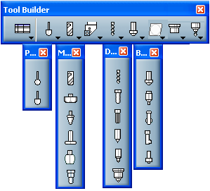
  3. Click the icon corresponding to the tool you want to create.

    The tool creation dialog box is displayed.

  4. A default name is proposed. You can edit it.

  5. Enter any comment you may need.

  6. When available:

    1. Select the Ball-end tool check box, to create one, if required.
    2. For a Multi-diameter Drill tool, enter the Number of stages.

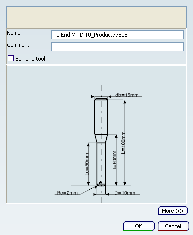
  7. Double-click any value in the icon representing the geometry of the tool to edit it in the dialog box that appears.

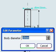
    The representation icon is updated with the new values.

  8. An alternative is to click More>>

    A Geometry, a Technology, a Feeds & Speeds and a Compensation tab are displayed.

    Note: The Compensation tab appears when you are editing a Tool Change.

  9. Go to the requested tab and modify the parameters as explained for the turning tools.

    See About Feeds and Speeds and Specifying the Tool Compensation.

  10. Click OK to create the tool and exit the dialog box.

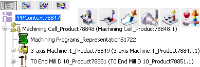
    It is added to the Machining Cell, for example as T0 End Mill D 10_xxx.

Edit a Tool

You can edit a tool from the Machining Cell.

  1. Right-click a tool in the Machining Cell and select NC Resources > Edit NC Resources

  2. Proceed as explained above for the creation.