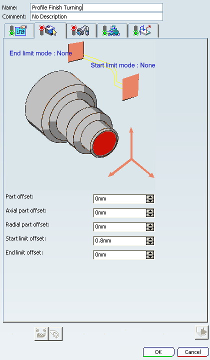
Profile Finish Turning | |||||||
|
| ||||||
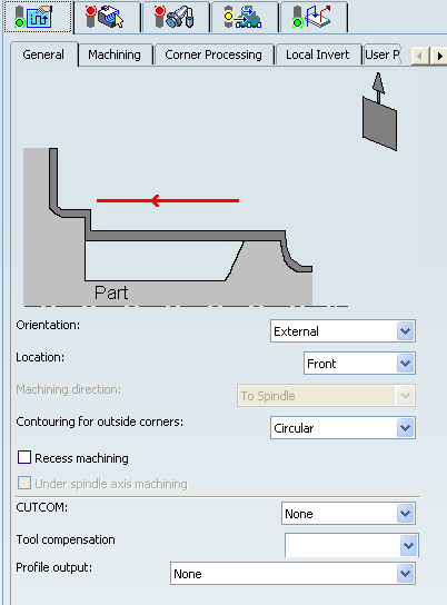
Strategy: General Parameters
- Tool Axis
- See Defining the Tool Axis
- Orientation
- Specifies the type of machining according to the
location of the area to machine on the part.
You can specify:
- Location
- Specifies location as:
- Front: The profile is machined toward the head stock.
- Back : The profile is machined from the head stock.
- Machining Direction
- Specifies the machining
direction with respect to the spindle axis. This option is only available for frontal orientation. You can specify:
- To Spindle
- From Spindle
Note: If start and end limit mode defined in Geometry tab are in conflict with the machining direction, then these can be reversed automatically.
- Contouring for Outside Corners
- Specifies contouring of corners as:
- Angular
- Circular
The part profile is respected in this case.
- Recess Machining
- Select this check box for a recess machining path after the profile
finish path.
Note: An asymmetric groove tool insert whose nose radius (left or right) is greater than half its width allows complete machining.
- Under Spindle Axis Machining
- Select this check box to request machining under the spindle axis. This option is available for the Frontal orientation.
- CUTCOM
- Specifies cutter compensation so that the NC output includes CUTCOM
instructions in approach and retract paths for cutter compensation.
You can specify:
- None
- On : CUTCOM/RIGHT instruction generated if tool is to the right of the tool path and CUTCOM/LEFT if tool is to the left of the tool path.
- Reverse: CUTCOM/RIGHT instruction generated if tool is to the left of the tool path and CUTCOM/LEFT if tool is to the right of the tool path.
- Tool Compensation
- Select a tool compensation number
corresponding to the desired tool output point.
The usable compensation numbers are defined on the tool assembly linked to the Machining Operation.
 By default,
the output point corresponding to type P9 can be used, if you do not select a tool compensation
number.
By default,
the output point corresponding to type P9 can be used, if you do not select a tool compensation
number. - Profile Output
- Select Profile Output on Part to compute tool path related to the profile output on part which is the resultant of the Part Geometry and the tool tip.
When Profile Output is set to Profile Output on Part, two tool paths are displayed during the Tool Path Replay, providing you with the visualization of the generated tool path position, of the part profile geometry using CNC machine controller and CUTCOM options:
- The tool path with respect to the Tool compensation point (orange color).
- The tool path related to the Profile Output on Part (while color).
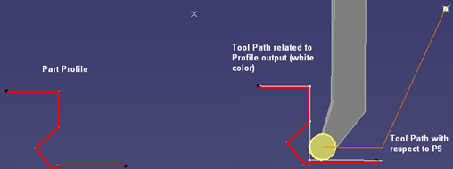
Without damaging the part, an interpolation is allowed wherever it is not possible to compute the tool path related to the Profile Output on Part, as explained below: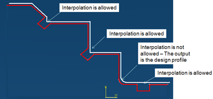
Profile Output on Part can be run with or without Recess machining.
With Recess machining selected: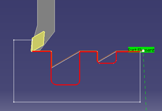
Although the Tool Path Replay shows both tool paths, the apt source output file contains the tool path corresponding to the Profile Output on Part with clear start and end blocks.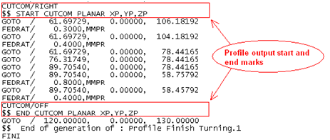
Use the options in the Corner processing tab to obtain a corner complying with the designer requirements.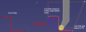
Simulation is done based on compensation point but not based on the Profile Output on Part.
Note: Local Invert is not supported for Profile Output.
![]()
Strategy: Machining Parameters
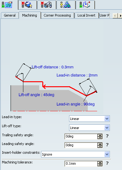
- Lead-in type
- Specifies the type of lead-in onto the profile at lead-in feedrate.
You can specify:
- Linear: Lead-in up to the point where profile machining start is defined by means of the Lead-in distance and Lead-in angle parameters.
- Circular: Lead-in is circular and tangent to the point where profile machining start. It is defined by means of the Lead-in radius and Lead-in angle parameters.
Note: The lead-in angle is defined with respect to the normal to the cutting direction. Range of lead-in angle is from -90 to 135 degrees for all tool types except for a grooving tool, where it ranges from 0 to 90 degrees.
The figure below shows how to set linear lead-in and circular lift-off.
- Lift-off type
- Specifies the type of lift-off from the profile at lift-off feedrate.
You can specify:
- Linear: Lift-off from the point where profile machining ends is defined by means of the Lift-off distance and Lift-off angle parameters.
- Circular: Lift-off is circular and tangent from the point where profile machining ends. It is defined by means of the Lift-off radius and Lift-off angle parameters.
Note: The lift-off angle is defined with respect to the normal to the cutting direction. Range of lift-off angle is from -90 to 135 degrees for all tool types except for a grooving tool, where it ranges from 0 to 90 degrees.
The figure below shows how to set circular lead-in and linear lift-off.
- Leading and Trailing Safety Angles
- The insert geometry is taken into account to avoid collision by reducing
the maximum slope on which the tool can machine. The Leading Safety Angle
and Trailing Safety Angle allow you to further
reduce this slope.
Leading and trailing angles can also be defined on the insert-holder to define the maximum slope on which machining can be done. In this case and if the Insert-Holder Constraints setting is applied, the angles that reduce the slope most are taken into account.
- Machining Tolerance
- Specifies the maximum allowed distance between the theoretical and computed tool path.
- Insert-Holder Constraints
- Specifies insert-holder constraints as:
- Ignore
- Apply
The following attributes (located on the Insert-holder's Technology tab) may influence machining: See Creating or Editing a Probing, a Milling, or a Drilling Tool
- Gouging angle
- Trailing angle
- Leading angle
- Maximum recessing depth
- Maximum cutting depth
- Maximum boring depth
These attributes take tooling accessibility into account and may reduce the machined area. However, you can use the Insert-Holder Constraints option to either ignore or apply these tooling attributes. You can replay the Machining Operation to verify the influence of these attributes on the generated tool path.
The Insert-Holder Constraints setting does not influence the Leading Safety Angle and Trailing Safety Angle.
![]()
Strategy: Corner Processing Parameters
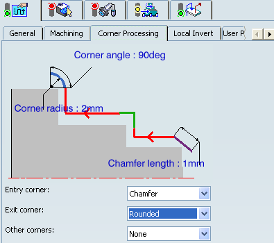
- Entry, Exit, and Other corners
- Entry
Corner means the first corner on the Part profile in the specified machining
direction and Exit
Corner means the last corner on the Part profile in
the specified machining direction. Corner processing
is proposed for Entry, Exit andOther corners. . The Entry/Exit corners are determined according to the specified
machining direction and not by the tool motion.
You can specify:
- None: No corners are to be machined along the profile.
- Chamfer: Only 90 degree corners of the profile are chamfered.
- Rounded: All corners of the profile are rounded.
The following options availability depends on the following conditions:
- Chamfer Length: If Other corner processing mode is Chamfer.
- Corner Radius: If Other corner processing mode is Rounded.
- Entry Corner Chamfer Length: On first flank of groove when Entry corner processing mode is Chamfer.
- Entry Corner Radius: On first flank of groove when Entry corner processing mode is Corner.
- Entry Corner Angle: On first flank of groove when Entry corner processing mode is Corner.
- Exit Corner Chamfer Length: On last flank of groove when Exit cornerprocessing mode is Chamfer.
- Exit Corner Radius: On last flank of groove when Exit corner processing mode is Corner.
- Exit Corner Angle: On last flank of groove when Exit corner processing mode is Corner.
![]()
Strategy: Local Invert Parameters
The inversion of elements is possible for Profile Finish Turning operations.
This is illustrated in the figure below: 
- Invert Lead-in angle
- Specifies Invert lead-in angle to provide angle control for Invert Lead-in dist parameter.
By default,
the Invert lead-in angle value is 90 degree.
- Invert Lead-in dist
- Specifies Invert lead-in distance to approach distance from the inverted profile.
- Invert Lift-off angle
- Specifies Invert lift-off angle to provide angle control for Invert Lift-off dist parameter.
By default,
the Invert lift-off angle value is 45 degree.
- Invert Lift-off dist
- Specifies the exit distance from the inverted profile.
- Invert Strategy
- Specifies the invert strategy.
To machine part with inverted elements, the following Invert strategies are available:
- Thickness: A given thickness is set on the inverted element and the remaining material is removed when the inverted element is machined again.
- Overlap: A given length of an element is machined twice (when the profile is machined and then when inverted elements are machined). In this case, you can choose to machine inverted elements first or machine them later.
- None: No invert strategy is applied.
- Machine inverted elements first
- Select this check box to machine the inverted elements in the first path, and then the other elements.
- Invert Lift-off type
- Specifies the type of entry and exit
motion.
You can specify:
- Linear motion defined by a distance and an angle.
- Circular motion defined by a radius and an angle.
Note: The lead-in and lift-off can be linear or circular as specified in the Machining tab.
![]()
Geometry
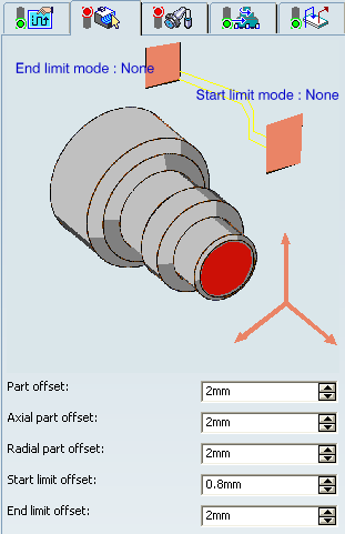
- Part profile
- Part profile is are required. It can be specified by selecting edges either directly or after selecting the By Curve contextual command in red part area.
- Limit Mode
- Start Limit Mode: This allows you to specify a point, line, curve, or face as the start element of the part profile. If a face is specified, the start element is the intersection of the face and the working plane. The position of the start of machining is also defined with respect to this element.
- End Limit Mode: This allows you to specify a point, line, curve or face as the end element of the part profile. If a face is specified, the end element is the intersection of the face and the working plane. The position of the end of machining is also defined with respect to this element.
You can specify In / On / Out settings for limit modes.
This setting allows you to specify the Go-Go type positioning of the tool with respect to the start element. Go-Go type positioning of tool in general positions the tool based on its radius and tool compensation number. This means positioning can vary for different tool insert geometries with respect to the limit and there is possibility of tool going beyond limit even with In option. The On option is always used for a point type start element.
Note: To avoid collisions of tool with limit geometry or unwanted machining beyond limits with In option, either define limits with suitable offset value or include limit geometry as part element (this is better wherever applicable) and avoid limit definition.
Relimiting the Area to Machine by means of Limit Mode:
- If you specify a point, it is projected onto the part profile. A line through the projected point parallel to the radial axis delimits the area to machine.
- If you specify a line, its intersection with the part profile is calculated (if necessary, the line is extrapolated). A line through the intersection point parallel to the radial axis delimits the area to machine.
- If you specify a curve, its intersection with the part profile is calculated (if necessary, the curve is extrapolated using the tangent at the curve extremity). A line through the intersection point parallel to the radial axis delimits the area to machine.
If needed, the profile may be extrapolated to the end element.
The figure above illustrates the use of start and end elements for Profile Finish Turning. Profile is machined from start element. Profile is extrapolated up to end element. Direct approach and radial-axial retract.- Part offset
- Specifies part offset perpendicular to the part profile.
- Axial part offset
- Specifies axial part offset perpendicular to the part profile.
- Radial part offset
- Specifies radial part offset perpendicular to the part profile.
- Start limit offset
- Specifies the distance with respect to the start element (only if start element is a line or a curve, and when In or Out is set for start element positioning).
- End limit offset
- Specifies the distance with respect to the end element
(only if end element is a line or a curve, and when In or Out is set for
end element positioning).
In addition to these global values, local offsets can be applied to segments, curves and arcs of the part profile.
![]()
Tools
The following tooling may be used:
- External
 and Internal
  insert-holders with all insert types except
groove
insert-holders with all insert types except
groove  and thread
  .
. - Internal
 , External
  Groove insert-holders with groove
and trigon
Groove insert-holders with groove
and trigon  inserts
For more information about tooling configuration, please refer to the Trigon Insert Used on a Groove Insert-holder.
See Specifying a Tool Element in a Machining Operation and Creating or Editing a Probing, a Milling, or a Drilling Tool.
![]()
Feedrates and Spindle Speed Parameters
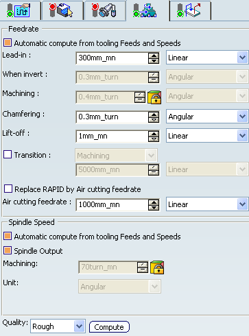
- Feedrate: Automatic compute from tooling Feeds and Speeds
- This check box allow a Machining Operation feeds and speeds values to be updated automatically when the tool's feeds and speeds values are modified.
You can specify the following feedrates:
- Lead-in
- When invert
- Machining
- Chamfering: Feedrate for machining chamfers or corners
- Lift-off
- Transition
- You can locally set the feedrate for a transition path to a Machining Operation B from a Machining Operation A or from a tool change activity. This is done by selecting the Transition check box in the Machining Operation dialog box for Machining Operation B.
- Replace RAPID by Air cutting feedrate
- Select this check box to replace RAPID feedrate in tool trajectories (except
in macros) by Air cutting feedrate.
The changes in unit of Air cutting feed-rate, are also reflected in APT file output. Calculated cycle time in Properties dialog box of the Machining Operation also get changed. There are changes in total time and machining time on Tool Path Replay dialog box.
Note:
The feedrates and Air cutting feedrate can be defined in linear (feed per minute) or angular (feed per revolution) units.
- Angular: feedrate in revolutions per minute and unit is set to mm_turn.
- Linear: feedrate in feed per minute and unit is set to mm_mn.
- Spindle Speed: Automatic compute from tooling Feeds and Speeds
This check box allow feeds and speeds values to be updated automatically when the tool's feeds and speeds values are modified.
If the Feedrate Automatic compute check box is selected and the Spindle Speed: Automatic compute from tooling Feeds and Speeds check box is not selected, then only the feedrate values can be computed. If both are not selected then automatic updating is not done.
When you modify a tool's feeds and speeds, all existing Machining Operations with the Automatic compute checkboxes selected that use this tool (or an assembly using this tool) can be recomputed.
- Spindle output
- This check box manage output
of the SPINDL instruction in the generated NC data file. The instruction is generated, if the check box is selected. Otherwise,
it is not generated
Note:
The spindle speed can be defined in linear (length per minute) or angular (length per revolution) units.
- Angular: length in revolutions per minute and unit is set to mm_turn.
- Linear: length in feed per minute and unit is set to mm_mn.
- Quality
- The feed and speed values are computed according to the Quality setting on the Machining Operation.
- Compute
- Feeds and speeds of the Machining Operation can be updated according to tooling feeds and speeds by clicking the Compute button.
Feeds and speeds of the Machining Operation can be updated automatically according to tooling data and the rough or finish quality of the Machining Operation. See About Feeds and Speeds.
![]()
Macro Parameters
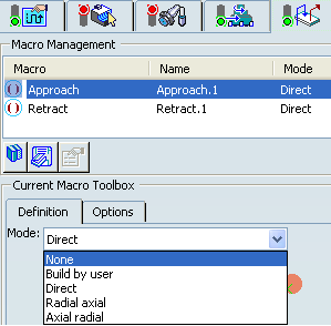
The selected macro type (Approach or Retract) defines the tool motion before
or after machining:
- Approach: to approach the Machining Operation start point.
- Retract: to retract from the Machining Operation end point.
The proposed macro mode are:
- None
- Build by user
- Direct
- Radial-axial
- Axial-radial
See Defining Macros.