Trigon Insert Used on a Groove Insert-holder | ||
| ||
Capabilities of Groove Insert-holder with Trigon Insert
Groove insert-holders support Groove inserts, Round Inserts, and Trigon inserts.
An Internal, Frontal, or External Groove insert-holder with a Trigon insert can be used in the following turning Machining Operations:
- Rough Turning
- Recess Turning
- Profile Finish Turning
- Groove Finish Turning
- Groove Turning
- Sequential Turning
All strategies supported by Groove insert-holder with Groove insert are also supported by Groove insert-holder with Trigon insert.
In addition the following capabilities are available with the Groove insert-holder with Trigon insert configuration:
- Collision avoidance with the part.
- Update of computed stock with such tools.
- Material removal simulation in video is supported with such tools.
![]()
Limitation when Using Groove Inserts
In general, it is recommended that the insert width of a groove insert is greater than the sum of the two nose radius values.
There is a limitation when you set one nose radius correctly for machining and then modifies the other nose radius: the computed tool path may not be correct when the modified radius is such that the insert width is equal (or almost equal) to the sum of the two radius values.
However, there is no problem when both radius values are equal and their sum equals the insert width.
![]()
Limitations of Groove Insert-holder with Trigon Insert
Some limitations exist due to an approximation of the tool insert in the algorithm.
-
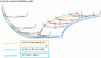
Trigon insert bottom angle is always 10 degrees. A shift exists at the insert bottom, which is taken into account in the computation.
This is particularly noticeable when machining low-slope-geometry shapes, that is, a shift is noticeable, in general, on inclined profiles and the shift is more, particularly, when machining profiles with comparitively less inclination.
-
Undercuts parts are not machined in groove finishing. The corresponding flank angles are set to 0 degrees instead of 20 degrees to avoid any risk of collision.
-
Twenty degrees are added from the real edge of the trigon insert when considering the gouging safety angle in the tool path computation.
