Rough Turning | |||||
|
| ||||
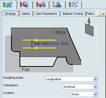
Strategy Parameters
- Tool Axis
- See Defining the Tool Axis
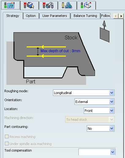
- Max Depth of Cut
- Specifies the maximum distance between passes.
- Axial and Radial Depth of Cut
- Specifies the maximum axial and radial distances between passes for Parallel Contour mode.
- Roughing Mode
- Specifies the roughing mode.
You can specify:
- Longitudinal
- Face
- Parallel Contour
- Location
- Specifies the location.
It determines the way the program closes the area to machine using radial, axial, axial-radial, or radial-axial relimitation. The following machining locations are proposed:
- Front: the part is machined toward the head stock.
- Back: the part is machined from the head stock.
- Orientation
- Specifies the orientation.
It determines the way the program closes the area to machine using radial, axial, axial-radial, or radial-axial relimitation. The selected orientation defines the type of geometric relimitation to be done between the stock and part geometry in order to determine the area to machine. The following Orientations are proposed:
- Internal
- External
- Frontal: This is available only with Face and Parallel Contour Roughing Mode.
Selected part and stock profiles do not need to be joined (see the following figures).
In Frontal machining, the minimum and maximum diameters of the area to machine are determined by the stock profile dimensions.
For example, in the following figure the area to machine is relimited by the spindle axis because the stock profile is also relimited by the spindle axis.
- Machining Direction
- Specifies the machining direction.
You can specify:
- Part Contouring
- Specifies a contouring type for Longitudinal and Face roughing mode
in order to clear the part profile by means of the following settings:
- No: no contouring
- Each path: profile following at each roughing pass.
- Last path only: profile following at last roughing pass only.
- Recess Machining
- Select this check box, if you require recess machining.
This check box is available if Part Contouring is Each path or Last path only. When recess machining is active in Parallel Contour roughing mode then Axial and Radial Depth of Cut must have suitable values to ensure a collision free tool path.
Recommendations for collision free Recess Machining in Parallel Contour roughing mode. Machining in Parallel Contour Rough turning is done by means of successive offsets of the tool path: the offset depends on the axial and radial depth of cut values. The following recommendations describe how to set the axial and radial depth of cuts to ensure a collision free tool path.
Parallel Contour Principle: The parallel contours of the tool path are obtained by first shifting the last pass then shifting each successive pass depending on the axial and radial depth of cut values.
Then the passes are relimited taking into account the stock definition.Correct Combination of Axial and Radial dDepth of Cuts: Compared with the left and right angles on the insert, the axial and radial depth of cut values define a shift direction that must be compatible with the insert.
The shift direction must be inside the limit angles defined on the tool insert otherwise a collision may occur. In collision cases, the collision is on the first pass, not on the last passes of the tool path.Example of a Correct Combination:
Example of an Incorrect Combination (Right of Tool):
The parallel contour tool path is in collision because the shift does not respect the tool insert angle on the right side.
- Under Spindle Axis Machining
- Select this check box to request machining under the spindle axis.
This is available with:
- Face roughing mode and Internal/External/Frontal orientation.
- Parallel Contour roughing mode and Frontal orientation.
- Tool Compensation
- Select a tool compensation number corresponding to
the desired tool output point.
The usable compensation numbers are defined on the tool assembly linked to the Machining Operation.
 By default,
the output point corresponding to type P9 can be used, if you do not select a tool compensation
number.
By default,
the output point corresponding to type P9 can be used, if you do not select a tool compensation
number.
- Change Output
- Select the
Change Output Point check box to automatically manage the change of output point.
.
If the output point is consistent with the flank of the recess to be machined, the output point is changed when the other flank of the recess is machined.
At the end of the Machining Operation, the output point is the same as it was at the start of the Machining Operation. See Tool Output Point Change.
![]()
Strategy: Option Parameters
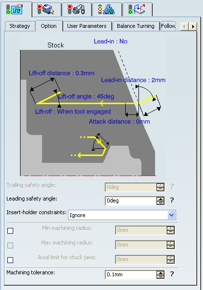
- Lead-in Distance and Lead-in Angle
- Specifies the lead-in vector at the start of each pass
with respect to the normal to the cutting direction.
Lead-in distance takes the stock profile and stock clearance into account. The tool is in RAPID mode before this distance.
If no lead-in angle is requested, the lead-in path is normal to the cutting direction. For Longitudinal and Face roughing mode the lead-in angle can be applied as follows:
- no angle applied to lead-in path
- lead-in angle applied to each path
- lead-in angle applied to last path only.
For Parallel Contour roughing mode, the lead-in angle is applied to each path.
- Distance before plunge and Angle before plunge
- Specifies the plunge vector before each new pass with respect to the cutting direction for Longitudinal and Face roughing mode.
- Attack Distance
- Specifies the attack distance with respect to the cutting direction and takes the stock profile and stock clearance into account.
- Lift-off Distance and Lift-off Angle
- Specifies the lift-off vector at the end of each pass with
respect to the cutting direction. and
For Longitudinal and Face roughing mode, lift-off occurs as follows.
- At the end of each pass when Part Contouring Type is set to None or Last path only.
- At the end of the last pass of the Machining Operation when the Part Contouring Type is set to Each path. This prevents the tool from damaging the part when returning to the end point in RAPID mode.
- At the end of each pass that ends on the stock profile.
For Parallel Contour roughing mode, lift-off occurs when the end of the pass has already been machined by a previous pass.
- Leading and Trailing Safety Angles
- The insert geometry is taken into account to avoid collision by reducing
the maximum slope on which the tool can machine. The Leading Safety Angle
and Trailing Safety Angle allows you to further
reduce the area to machine.
The Trailing Safety Angle can be used only when Recess Machining is
set.
Leading and trailing angles can also be defined on the insert-holder to define the maximum slope on which machining can be done. In this case and if the Insert-Holder Constraints setting is applied, the angles that reduce the slope most is taken into account.
- Insert-Holder Constraints
- Specifies insert-holder constraints as:
- Ignore
- Apply
The following attributes (located on the Insert-holder's Technology tab) may influence machining: See Creating or Editing a Probing, a Milling, or a Drilling Tool:
- Gouging angle
- Trailing angle
- Leading angle
- Max Recessing Depth
- Maximum Cutting Depth
- Maximum Boring Depth
These attributes take tooling accessibility into account and may reduce the machined area. However, you can use the Insert-Holder Constraints option to either ignore or apply these tooling attributes. You can replay the operation to verify the influence of these attributes on the generated tool path.
The Insert-Holder Constraints setting does not influence the Leading and Trailing Safety Angles.
- Minimum Machining Radius
- Specifies the maximum machining radius.
This option is available when Orientation is External.
- Maximum Machining Radius
- Specifies the maximum internal machining radius.
This option is available with Face roughing mode, Internal/Frontal orientation, and From Spindle machining direction.
Note: Maximum boring depth is defined on the tool.
- Axial Limit for Chuck Jaws
- Specifies the axial limits for external or frontal machining.
Offset can be defined from the machining axis system.
- Machining Tolerance
- Specifies the maximum allowed distance between the theoretical and computed tool path.
![]()
External Longitudinal Rough Turning
In the figure above the tool motion is as follows:
- approach in RAPID mode
- lead-in at the first recess pass and plunge approach for other passes
- plunge at plunge feedrate
- machine at machining feedrate
- contouring at contouring feedrate
- lift-off at last recess pass at lift-off feedrate.
Note: Trailing angle is defined on the tool.
![]()
Balance Turning
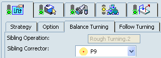
- Sibling Operation
- Displays the name of created sibling Machining Operation.
- Sibling Corrector
- Specifies all the available tool compensations on the sibling tool.
![]()
Follow Turning
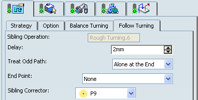
- Sibling Operation
- Displays the name of created sibling Machining Operation.
- Delay
- Specifies the delay (in linear unit) to start the slave passes.
- Treat Odd Path
- Specifies strategy for the odd
path. You can specify:
- Alone at the Start: Odd pass corresponding to the master is always the first pass.
- Alone at the End: Odd pass corresponding to the master is the last pass.
- End Point
- Specifies synchronization end point. You can specify:
- None: No synchronization at the end of passes.
- End Of Lift Off: Synchronization at the end of Lift Of of both Machining Operations.
- Sibling Corrector
- Specifies all the available tool compensations on the sibling tool.
![]()
Geometry
- Part profile
- Part and stock profiles are required. They can be specified by selecting
edges either directly or after selecting the By Curve contextual
command in red part area.
See Selecting Edges and Faces to Define Geometry.
Multiple areas are not managed. If a profile with multi-domains is selected manually or by means of the automatic stock selection capability, only a single area is taken into account for machining.
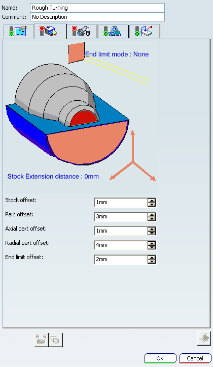
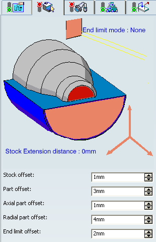
- End limit mode
The End Limit option allows you to specify a point, line, curve, or face to relimit or extrapolate the selected part profile. This also relimits the input stock. If a face is specified, the end element is the intersection of the face and the working plane. The position of the end of machining is defined with respect to this element by one of the following settings: None / In / On / Out. The part profile is relimited or extrapolated in this direction. The input stock is also relimited by end element in this direction.
Note: The location of end limit is based on the direction of machining as shown in the image of Strategy tab. The following image displays the machining direction for Longitudinal Roughing mode, External Orientation, and Front Location Strategy.
Relimiting the Area to Machine using Limit Mode
If you specify a point, it is projected onto the part profile. A line through the projected point parallel to the radial axis delimits the area to machine.
If you specify a line, its intersection with the part profile is calculated (if necessary, the line is extrapolated). A line through the intersection point parallel to the radial axis delimits the area to machine.
If you specify a curve, its intersection with the part profile is calculated (if necessary, the curve is extrapolated using the tangent at the curve extremity). A line through the intersection point parallel to the radial axis delimits the area to machine.
- Stock Extension distance
- This allows
you to extend the stock in the machining direction and, to any desired length.
This can be useful in Rough Turning scenarios, where you want to machine beyond the stock profile. This extension is taken into account for tool path computation when an end limit element is defined and used on the operation (when End limit mode is different from None).
The extension distance defines the extended domain for tool path computation. The end limit is respected only when it is specified (according to the In / On / Out mode) inside the extended domain.
The figures below show that an End limit is defined (selected and mode different from None) and a Stock Extension distance is defined (greater than 0).
The tool moves beyond the stock (extension distance). This distance defines the machining domain extension for tool path computation.
In this particular case, the End limit is not reached (In / On / Out) because it is outside the extended machining domain.
In the following examples, the following key is used to illustrate various cases of stock extension:
Example 1: End limit beyond stock with no stock extension.
Example 2: End limit beyond stock but inside stock extension.
Example 3: End limit beyond stock and stock extension.
Example 4: Stock extension with no End limit.
Example 5: End limit inside stock and no stock extension.
- Stock offset
- Specifies a virtual displacement of the stock profile.
- Part offset
- Specifies a virtual displacement of the part
profile.
- Axial part offset
- Specifies a virtual displacement of the
part profile along the spindle axis direction.
The following image shows offset of a part (located initially at Zero offset) due positive and negative Axial part offset value. This is applicable in general for any Orientation Strategy parameter .i.e. External, Internal etc.
- Radial part offset
- Specifies a virtual displacement of the
part profile in the radial axis direction.
Offsets can be positive or negative with any absolute value. The global offset applied to the part profile is the resulting value of the normal, axial and radial offsets.
The following image shows offset of a part (located initially at Zero offset) due positive and negative Radial part offset value. This is applicable in general for any Orientation Strategy parameter .i.e. External, Internal etc.
- End Limit Offset
-
Specifies the distance with respect to the end element
(only if end element is a line or a curve, and when In or Out is set for
end limit positioning).
Offsets can be positive or negative with any absolute value. The global offset applied to the part profile is the resulting value of the normal, axial, and radial offsets.
![]()
Tools
The following tooling may be used:
- External
 and Internal
  insert-holders with all insert types except
groove
insert-holders with all insert types except
groove  and thread
  .
. - External
 and Internal
  Groove insert-holders with groove and trigon
 inserts.
For more information about tooling configuration, please refer to the Trigon Insert Used on a Groove Insert-holder.
inserts.
For more information about tooling configuration, please refer to the Trigon Insert Used on a Groove Insert-holder.
See Specifying a Tool Element in a Machining Operation and Creating or Editing a Probing, a Milling, or a Drilling Tool.
![]()
Feedrates and Spindle Speed Parameters
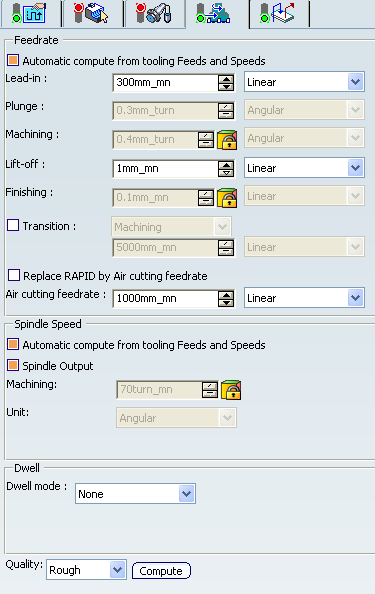
- Feedrate: Automatic compute from tooling Feeds and Speeds
- This check box allow a Machining Operation feeds and speeds values to be updated automatically when the tool's feeds and speeds values are modified.
You can specify the following feedrates:
- Lead-in: Applied during the lead-in and attack distance.
- Plunge: for longitudinal and face Rough Turning.
- Machining
- Lift-off
- Finishing
- Contouring Feedrate: If contouring type is Each Path or Last Path Only.
- Transition
- You can locally set the feedrate for a transition path to a
Machining Operation B from a Machining Operation A or from a tool
change activity. This is done by selecting the Transition check box in the Machining Operation dialog box for
operation B.
For more information, please refer to the Setting a Transition Feedrate.
- Replace RAPID by Air cutting feedrate
- Select this check box to replace RAPID feedrate in tool trajectories (except
in macros) by Air cutting feedrate.
The changes in unit of Air cutting feed-rate, are also reflected in APT file output. Calculated cycle time in Properties dialog box of Machining Operation also get changed. There are changes in total time and machining time on tool path replay dialog box.
Note:
The feedrates and Air cutting feedrate can be defined in linear (feed per minute) or angular (feed per revolution) units.
- Angular: feedrate in revolutions per minute and unit is set to mm_turn.
- Linear: feedrate in feed per minute and unit is set to mm_mn.
- Spindle Speed: Automatic compute from tooling Feeds and Speeds
This check box allow a Machining Operation feeds and speeds values to be updated automatically when the tool's feeds and speeds values are modified.
If the Feedrate Automatic compute check box is selected and the Spindle Speed: Automatic compute from tooling Feeds and Speeds check box is not selected, then only the feedrate values can be computed. If both are not selected then automatic updating is not done.
When you modify a tool's feeds and speeds, all existing Machining Operations with the Automatic compute checkboxes selected that use this tool (or an assembly using this tool) can be recomputed.
- Spindle output
- This check box manage output
of the SPINDL instruction in the generated NC data file. The instruction is generated, if the check box is selected. Otherwise,
it is not generated
Note:
The spindle speed can be defined in linear (length per minute) or angular (length per revolution) units.
- Angular: length in revolutions per minute and unit is set to mm_turn.
- Linear: length in feed per minute and unit is set to mm_mn.
- Dwell mode
- Dwell setting
indicates whether the tool dwell at the end of each path is to be set in
seconds or a number of spindle revolutions.
Decimal values can be used for the number of revolutions. For example, when machining big parts that have a large volume, it can be useful to specify a dwell using a value of less than one revolution (0.25, for example).
- Quality
- The feed and speed values are computed according to the Quality setting on the Machining Operation.
- Compute
- Feeds and speeds of the Machining Operation can be updated according to tooling feeds and speeds by clicking the Compute button.
Feeds and speeds of the Machining Operation can be updated automatically according to tooling data and the rough or finish quality of the Machining Operation. For more information, please refer to the About Feeds and Speeds.
![]()
Macro Parameters
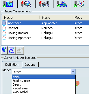
The selected macro type (Approach or Retract) defines the tool motion before
or after machining:
- Approach: to approach the Machining Operation start point.
- Retract: to retract from the Machining Operation end point.
The proposed macro mode are:
- None
- Build by user
- Direct
- Radial-axial
- Axial-radial
Linking macros, which comprise retract and approach motion can also be used on Rough Turning operations. Approach and retract motions of linking macros are interruptible. It can be useful to interrupt a Machining Operation when the foreseeable lifetime of the insert is not long enough to complete the machining. See Defining Macros.