Creating a Profile Contouring Operation: Trim Between Curves and Surfaces | ||||||
|
| |||||
Activate the Manufacturing Program and click Profile Contouring
 in the Prismatic Machining Operations toolbar.
A Profile Contouring entity is added to the Manufacturing Program. The Profile Contouring dialog box appears directly at the Geometry tab
 .
.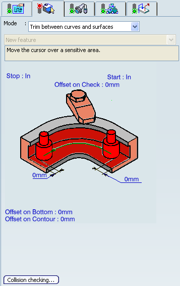
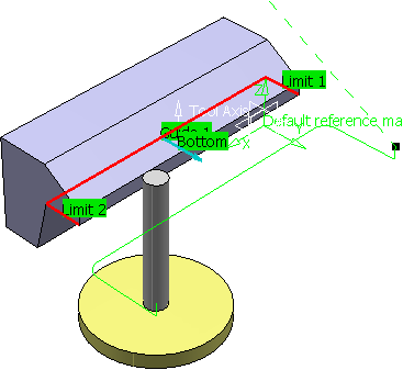
The top guiding curve and part bottom in the icon are colored red indicating that this geometry is required for defining the operation. All other geometry is optional.
Still in the Geometry tab:
- Set the Contouring mode to Trim between curves and surfaces.
- Click the red bottom in the icon, then select the bottom surface of the part in the authoring window.
- Click top guiding curve in the icon, then select the top edge of the part in the authoring window.
- Click the first relimiting element in the icon, then select a vertical edge at one end of the part in the authoring window.
- Click the second relimiting element in the icon, then select the vertical edge at the other end of the part in the authoring window.
- If needed, set offset on the geometric elements.
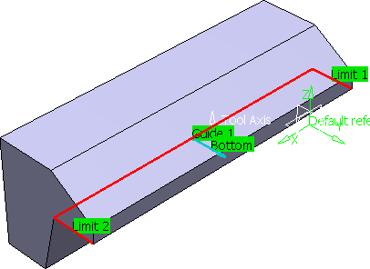
The guide and limit elements of the icon are now colored green indicating that this geometry is now defined. These are also indicated on the part.
Note: A Collision Checking capability is available in the Geometry tab, which allows collision checking between the tool and guide elements during macro motions.
- Choose the desired Tool path style.
- Set the machining criteria.
- Machining Parameters such as machining tolerance
- Stepover Parameters
- Finishing Parameters
- HSM Parameters
- User Parameters
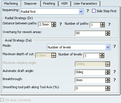
Note: The 3/5-Axis Converter is not supported and is disabled.
Go to the Tool tab
 and select a T- Slotter tool with a diameter of 30mm.
See Specifying a Tool Element in a Machining Operation
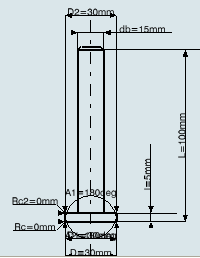
Note:
- The difference in cutting part between Z and -Z orientation is not supported properly.
- RC and RC2 must have same value.
Select the Feeds and Speeds tab
 to specify the feedrates
and spindle speeds for the operation.
to specify the feedrates
and spindle speeds for the operation.Select the Macro tab
 to add approach and retract motions to the operation.
Note: When macros are used, the surface selected as bottom is checked for collisions.
See Defining Macros on Milling Operations
Note:
- We recommend that you define the horizontal motion first
 , to avoid collision with the undercut.
 - The axial motions
 are defined according to the tool axis defined in the machining operation.
 - The ramping motion
 , helix motion
  , and add tool axis motion
  are not supported.
- We recommend that you define the horizontal motion first
Click Tool Path Replay
 to check the validity of the operation.
- The tool path is computed.
- A progress indicator is displayed.
- You can cancel the tool path computation at any moment before 100% completion.
 .
.