Selecting Geometry | |||
| |||
From any product or 3D part
- Alternatively, open an existing Machining Process or PPR context .
 By default,
the
Activities Process Tree opens
automatically.
By default,
the
Activities Process Tree opens
automatically.
- Alternatively, open an existing Machining Process or PPR context .
Click one of those icons to access the Machining Operations icons:
 Prismatic Machining Operations
 Surface Machining Operations
 Lathe Machining Operations
 Axial Machining Operations
The corresponding Machining Operations icons are displayed in a toolbar
Click any Machining Operation icon and select a Manufacturing Program or another Machining Operation in the Activities Process Tree.
- The dialog box opens at the Geometry
tab
 .
. - This page includes a sensitive icon to help you specify the geometry to be machined. The red status light on the tab indicates that you must select the geometry in order to create the operation.
Note:
- Each Machining Operation offers its own sensitive icon. In
addition, the icon is slightly different if you are using a rework
area or a slope area and will have fewer parameters.
- Initial sensitive icon for Sweeping:
- The same icon with a rework area:
- Initial sensitive icon for Sweeping:
- If you are editing a rework or a slope area, an additional
information is displayed, indicating which type of subset you are
working on. This field is not editable (you can not go from one
subset to another).

- The dialog box opens at the Geometry
tab
Select a part to machine:
Select another geometry:
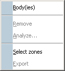
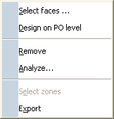
- Right-click an element definition area: choose Body(ies) in the
contextual menu if you wish to machine a whole part and not just an
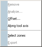
area on it, or Select zones if you wish to select zones.
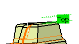
- Choose a pre-defined area like this:
Note:
- You can use Offset Groups and Features when defining geometry.
- The types of selection by default (reached by clicking a sensitive zone) are adapted to the types of the elements to select (bodies for a part to machine, but faces for check elements, for instance).
- The contextual menus vary also with the type of elements to select.
- Set an offset on all of the planes using the contextual menu over
each plane. The offset can be either positive or negative and is
previewed in the authoring window before it is validated.
In the case of imposed planes, the offset value applies to all of the planes you have imposed. The tool passes through all of the planes defined by the offset and not through the planes that are imposed. One advantage of this is that if the top surface of the part is flat and you have defined an Offset on part of, for example of 1mm, you can define the same offset on the imposed planes so as to ensure that there will be no residual material remaining on the top surface.
- Right-click an element definition area: choose Body(ies) in the
contextual menu if you wish to machine a whole part and not just an
area on it, or Select zones if you wish to select zones.
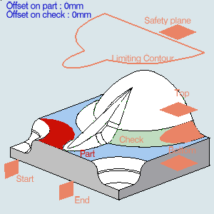
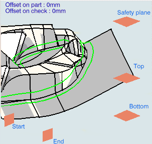
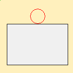
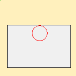
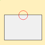
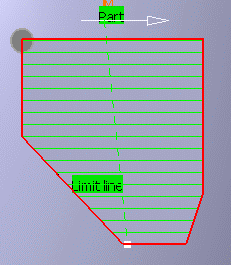
Use Part autolimit and the limiting contour individually or together to define the area you want to machine.
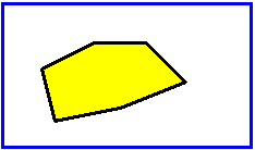
In the pictures:
- the blue outline is the part edge,
- the yellow part is the area that will be machined,
- the black line is the limiting contour:
- if you activate Part autolimit, the
yellow area (shown in the image below) is machined and the tool
contact point stops on the edge of the part (the tool will not go
beyond the edge of the part).

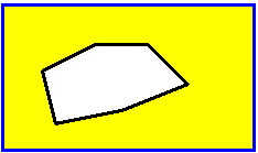
- If you use a limiting contour, only the area inside
the limiting contour is machined.
- If you wish to machine the area outside the limiting contour,
choose Outside as the Side to machine.
- if you activate Part autolimit, the
yellow area (shown in the image below) is machined and the tool
contact point stops on the edge of the part (the tool will not go
beyond the edge of the part).
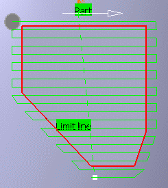
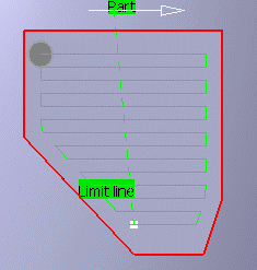
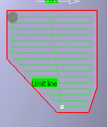
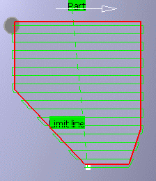
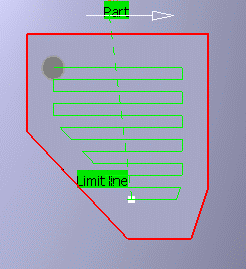
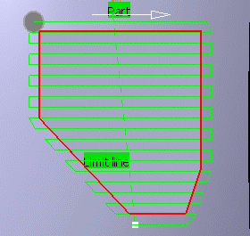
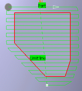
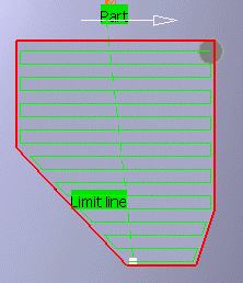
Once the limiting contour is defined, you can also define the following parameters:
- Stop position:
Specifies
where the tool stops:
- Outside stops the tool outside the limit
line,
- Inside stops the tool inside the limit line,
- On stops the tool on the limit line.
- Outside stops the tool outside the limit
line,
- Offset
: Starting
from the previous position (Inside, Outside,
On) a positive value of the offset increases the area to
machine, a negative value reduce this area:
- Stop position=On, no Offset
- Stop position=On, Positive Offset
- Stop position=On, Negative Offset
- Stop position=Inside, no Offset
- Stop position=Inside, Positive Offset
- Stop position=Inside, Negative Offset
- Stop position=Outside, no Offset
- Stop position=Outside, Positive Offset
- Stop position=Outside, Negative Offset
- Stop position=On, no Offset
- Stop position:
Specifies
where the tool stops:
You can now either:
- run the operation on the part,
- store the operation that you have just defined, or
- define other parameters in the machining strategy, tool data, speeds and rates, or macro data tabs first.