Defining Macros on Milling Operations | ||||||
|
| |||||
From any product:
- Alternatively, open an existing Machining Process or PPR context .
 By default,
the
Activities Process Tree opens
automatically.
By default,
the
Activities Process Tree opens
automatically.
- Alternatively, open an existing Machining Process or PPR context .
Activate the Manufacturing Program.
- Click
 Axial Machining Operations.
 - Click
 Drilling in the sub-toolbars that appear.
 - Go to the Macros tab
 in the Machining Operation dialog box that appears.
The initial status of all the macros in the Macro Management list is Inactive
 .
.
- Click
Right-click the Approach macro line and select Activate in the contextual menu.
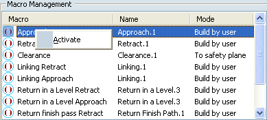
The macro line is activated.
turns to  , meaning some definition data exist but may require modifications.
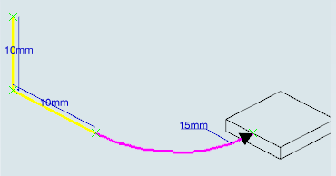
In the Current Macro Toolbox, select the Circular horizontal axial mode from the list.
A sensitive icon representing the 3 elementary paths of this macro appears.
Double-click each elementary path to display a dialog box that allows you to specify the exact characteristics the path.
The current elementary path is displayed in magenta.
- In the dialog box corresponding to the circular path, set the Radius to 15 mm
to have a 10mm vertical path followed by a 15mm radius circular path.The sensitive icon is updated.
- In the dialog box corresponding to the circular path, set the Radius to 15 mm
Click Tool Path Replay
 to check the circular approach.
 The yellow light turns to green, meaning the data are up-to-date.
Under Macro Management, as you did above:
- Activate the Linking Retract
macro line and select Axial. Assign a 20mm value to the retract path.
The Linking Approach/Retract macros have a common behavior and are seen as the same object. It allows to handle Activate/Deactivate for both Approach and Retract. Consequently, they share the same name and it is not possible to rename one independently from the other. The same applies to Between passes and Between passes link macros.
- Activate the Linking Retract
macro line and select Axial. Assign a 20mm value to the retract path.
In the Options tab, select the Cornerized clearance with radius check box, then enter a corner radius value of 3mm.
In the Tool Path Replay dialog box, select the Different colors mode
 in order to visualize feedrate changes. See Color Modes.
The tool path is displayed with the following default colors:
- Yellow: approach feedrate
- Green: machining feedrate
- Blue: retract feedrate
- Red: Rapid feedrate
- White: user-defined feedrate.
Note: Transition Paths are represented by dashed white lines.
The status of the macros are now Up to date.