Profile Contouring | |||||
|
| ||||
Machining Strategy Parameters
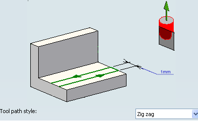
- Tool path style
- Specifies the tool path style.
- Zig Zag: The machining direction is reversed from one path to the next.
- One way: The same machining direction is used from one path to the next.
- Helix: In Between Two Planes machining mode, machining is done by maintaining constant tool contact with the part (reduction of air time). Multiple radial passes are possible with control of maximum ramping angle and maximum depth of cut. Helical interpolation instructions can be generated in the output file (APT source and Clfile) for helical tool motions.
- Tool Axis
- See Defining the Tool Axis
![]()
Machining Parameters
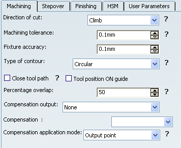
- Direction of cut
- Specifies how machining is to be done.
The options in the Direction of cut dropdown combo box are as follows:
- In Climb milling, the front of the advancing tool (in
the machining direction) cuts into the material first.
- In Conventional , the rear of the advancing tool (in
the machining direction) cuts into the material first.
- In Climb milling, the front of the advancing tool (in
the machining direction) cuts into the material first.
- Machining tolerance
- Specifies the maximum allowed distance between the theoretical and computed tool path.
- Fixture accuracy
- Specifies
a tolerance applied to the fixture thickness:
- If the distance between the tool and fixture is less than fixture thickness minus fixture accuracy, the position is eliminated from the trajectory.
- If the distance is greater, the position is not eliminated.
- Type of Contour
- Specifies the type of contour.
The options in the Type of contour dropdown combo box are as follows:
- Circular: the tool pivots around the corner point, following
a contour whose radius is equal to the tool radius
- Angular: the tool does not remain in contact with the
corner point, following a contour comprised of two line segments
- Optimized: the tool follows a contour derived from the
corner that is continuous in tangent
- Forced circular: This option may be used in certain complex
cases when the Circular option does not give satisfactory results. It
creates tool paths comprising of portions of circular arcs (for example,
when grooves are present along the trajectory and the tool is too big
to penetrate).
- Circular: the tool pivots around the corner point, following
a contour whose radius is equal to the tool radius
- Close tool path
- Select this check box to specify
whether or not the program must close the tool path.
- Close tool path is selected:
- Close tool path is not selected:
- Close tool path is selected:
- Tool position ON guide
- Select this check box to specify the position of the tool tip on the guiding elements. Offset on contour and driving mode are already taken into account.
- Percentage overlap
- Specifies
the amount that the tool must go beyond the end point of a closed tool path
according to a percentage of the tool diameter.
- Compensation output
- The options in the
Compensation output dropdown combo box manage the generation of cutter compensation (CUTCOM) instructions
in the NC data output in Between Two Planes machining mode
The options are:
- 2D Radial profile: Both the tool tip and cutter profile
can be visualized during tool path replay. Cutter compensation instructions
are automatically generated in the NC data output. An approach macro
must be defined to allow the compensation to be applied.
Note that only Circular contouring type is supported with this output
type.
Example of generated APT source:
$$ Start generation of : Profile Contouring.1
FEDRAT/ 1000.0000,MMPM
SPINDL/ 70.0000,RPM,CLW
CUTCOM/LEFT
$$ START CUTCOM PLANAR XP, YP, ZP
GOTO / 100.00000, -115.00000, 10.00000
GOTO / 0.00000, -115.00000, 10.00000
CUTCOM/OFF
$$ END CUTCOM PLANAR XP, YP, ZP
$$ End of generation of : Profile Contouring.1
Note: A negative Offset on contour (parameter in Geometry tab) is possible for 2D radial profile output.
- 2D Radial tip: The tool tip can be visualized during
tool path replay. Cutter compensation instructions are automatically
generated in the NC data output. An approach macro must be defined to
allow the compensation to be applied.
Example of generated APT source:
$$ Start generation of : Profile Contouring.1
FEDRAT/ 1000.0000,MMPM
SPINDL/ 70.0000,RPM,CLW
CUTCOM/LEFT
$$ START CUTCOM PLANAR XT, YT, ZT
GOTO / 100.00000, -125.00000, 10.00000
GOTO / 0.00000, -125.00000, 10.00000
CUTCOM/OFF
$$ END CUTCOM PLANAR XT, YT, ZT
$$ End of generation of : Profile Contouring.1
- None: cutter compensation instructions are not automatically generated in the NC data output. However, CUTCOM instructions can be inserted manually. For more information, refer to Procedure for Generating CUTCOM Syntaxes.
Note: The PP words in macros you define are added to the cutter compensation instructions generated in the NC data output. Therefore be careful when specifying CUTCOM instructions in macros.
- 2D Radial profile: Both the tool tip and cutter profile
can be visualized during tool path replay. Cutter compensation instructions
are automatically generated in the NC data output. An approach macro
must be defined to allow the compensation to be applied.
Note that only Circular contouring type is supported with this output
type.
![]()
Stepover Parameters
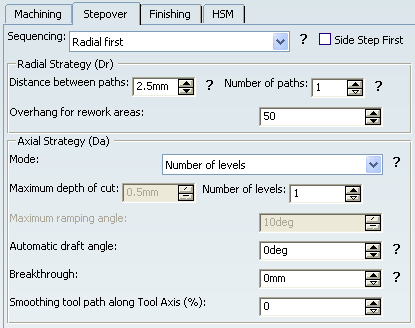
- Sequencing
- Specifies the order
in which machining is done.
The options in the Sequencing dropdown combo box are as follows:
- Axial First: axial machining is done first then radial.
- Radial First: radial machining is done first then axial.
- Axial First: axial machining is done first then radial.
- Side Step First
- On selecting this check-box, each disconnected
guide is handled for all the passes (radial, axial, and finishing)
and then the tool moves to the next guide and finishes all the passes for that guide.
For a given contour, the sequence of passes is defined by the Sequencing option.
If the guides are not disconnected and this check box is selected, no change occurs in the tool path.
Note: This option does not apply to Profile Contouring Operation: By Flank Contouring. The check-box is disabled in this mode.
 By default,
this check box is not selected
for newly created operations.
By default,
this check box is not selected
for newly created operations.
- Distance between paths
- Specifies
the maximum distance between two consecutive tool paths in a radial strategy.
- Overhang for rework areas
- Allows a shift in the tool position with respect to the soft boundary of the rework area.
- Axial strategy mode
- Specifies
how the distance between two consecutive levels is computed.
The options in the Axial strategy mode dropdown combo box are as follows:
- Maximum depth of cut
- Number of levels
- Number of levels without top
- Maximum ramping angle
- Specifies the maximum ramping angle. This option is available when Tool Path Style is Helix in Between two planes mode.
- Automatic draft angle
- Specifies the draft angle to be applied on the flanks between the top and bottom elements.
- Breakthrough
- Specifies the
distance in the tool axis direction that the tool must go completely through
the part.
- It is available in Between two planes mode.
- It is applied on the bottom element, which must be specified as soft.
- Smoothing Tool path along Tool Axis (%)
- Specifies the value to smooth the tool path when the tool path is going rapidly from a direction into a Z direction, without transition.
If you specify the value as N%, the existing tool path points, within an area of size N% of tool diameter centered on the tool path discontinuity, are moved along the tool axis to smooth the tool path.
By default,
the value is 0%.
![]()
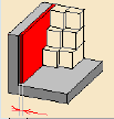
Finishing Parameters
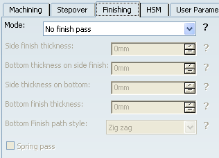
- Mode
- Specifies
whether
or not finish passes are to be generated on the sides and bottom of the
area to machine.
The options in the Finishing mode dropdown combo box are as follows:
- No finish pass
- Side finish last level
- Side finish each level
- Finish bottom only
- Side finish at each level & bottom
- Side finish at last level & bottom
- Side finish thickness
-
Specifies the thickness of material that can be machined by the side finish
pass.
- Bottom thickness on side finish
- Specifies the thickness of material left on the bottom by the last side
finish pass.
In short, Bottom finishing can be done without any side finishing or with different combinations of side finishing.
- Side thickness on bottom
- Specifies the thickness of material left on the side by the bottom finish
pass.
- Bottom finish thickness
-
Specifies the thickness of material that can be machined by the bottom
finish pass.
![]()
HSM Parameters
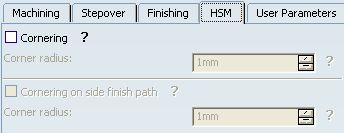
- Cornering
- Select this check box to specify whether
or not cornering for HSM is to be done on the trajectory.
In a Profile Contouring, cornering for HSM is available for the roughing and finishing passes in the following guiding modes:
- Between two planes
- Between curve and surfaces
- Between two curves.
Cornering applies to inside corners for machining or finishing passes. It does not apply to:
- outside corners (for example, produced by angular or optimized contouring mode).
- macros or default linking and return motions.
- Corner radius
- Specifies the
radius used for rounding the corners along the trajectory of a HSM operation.
Note: Value must be smaller than the tool radius.
![]()
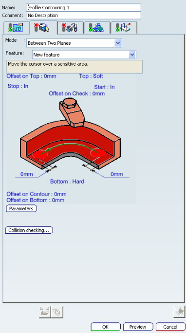
Geometry
- Mode: Between Two Planes
- The tool follows a contour between top and bottom planes while respecting user-defined
geometry limitations and machining strategy parameters. The options in the
Mode: Between Two Planes dropdown combo box are as follows.
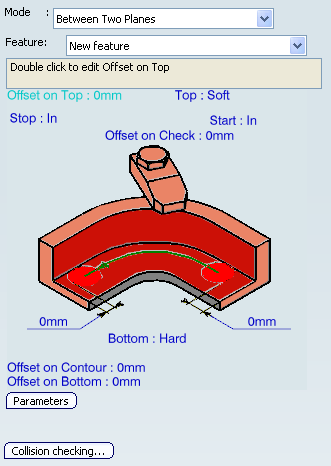
- Top plane with possible Offset on Top. Top may be Hard or Soft.
- Start and Stop relimiting elements with possible Offsets.
The In/On/Out setting allows you to specify the Go-Go type positioning of the tool with respect to the end element.
- Check elements with possible Offset on Check.
- Bottom (planar face or surface) with possible Offset on Bottom. Bottom may be Hard or Soft.
- Guide contour (edges or sketch) with possible Offset on Contour.
- Mode: Between Two Curves
- The tool follows a trajectory defined by the guide contour and auxiliary
guide contour while respecting user-defined geometry limitations and machining
strategy parameters. The options in the
Mode: Between Two Curves dropdown combo box are as follows:
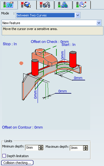
- Start and Stop relimiting elements with possible Offsets.
The In/On/Out setting allows you to specify the Go-Go type positioning of the tool with respect to the end element.
- Check elements with possible Offset on Check.
- Guide contour and Auxiliary Guide contour (edges or sketch) with
possible offsets:
- a global radial Offset on Contour
- an Axial Offset 1, the Guide contour
- an Axial Offset 2, the Auxiliary Guide contour
- Guide contour is used for positioning the flank of the tool (radial positioning).
- Auxiliary Guide contour is used for positioning the tool tip along the
tool axis (axial positioning).
Note: when only the Guide contour is specified:
- If no Auxiliary Guide contour is specified, the Guide contour is used for positioning both the flank and the tip of the tool.
- If no Auxiliary Guide contour is specified, but an Auxiliary Guide contour offset (Axial Offset 2) is specified and it is different from the Guide contour offset (Axial Offset 1), the machining domain is defined between Guide contour Axial Offset 1 and Axial Offset 2 applied to the selected Guide contour.
- Only one contour geometry selection is necessary to define a multi-level
tool path.
This is useful when the Guide contour is selected and there is no suitable
auxiliary guide curve on the geometry to machine. In this case, specify
the Number of levels in the Stepover tab. See example
below.
- Limits: You can restrict machining to a specific zone by specifying Minimum depth and Maximum depth values. The depths are taken from the Guide contour. The Depth limitation check box must be activated in this case.
- Side to Machine Control
You can specify the material side by selecting one or several points (vertices or Part Design points) in the authoring window.
The contextual menu for material side point is
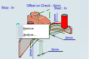
- Remove: Remove all the selected points mentioned for material side.
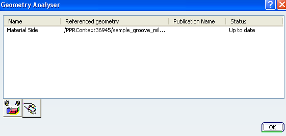
- Analyze: Geometry Analyser dialog box appears containing the selected material side points.
Note: The side to machine for the Profile Contouring operation depends on a number of factors like the tool axis, the tangent of the selected curve, the sequence of curve selection, etc.
Any change in the side to machine parameter requires a tool path re-computation to experience the effect of this parameter.
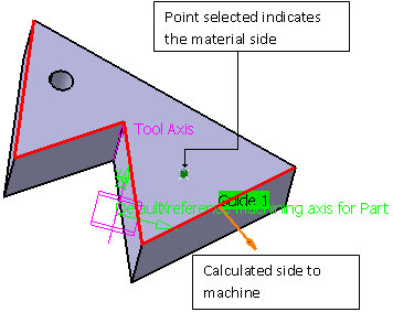
The side to machine is on the opposite side of the material side as compared to the guiding curve when looking along the tool axis direction.
In the example below, you have selected the guide and the point indicating the material side. Based on this additional input, the side to machine can be calculated as shown below. The point is projected in the plane perpendicular to the tool axis, the side to machine is the opposite of the side of the point compared to the guiding curve.
Selecting more than one point to indicate the material side is helpful in the case of disconnected contours or guides (that is, more than one guide is present in the operation).
If the projected point lies on the contour, it does not allow the system to determine the side to machine. You have to ignore this point.
Only one point (the closest one) can be associated to a contour. A point can be associated to more than one contour.
If more points than the number of disconnected contours are selected, the additional points are ignored. These ignored points can be seen in the Geometry Analyzer dialog box.
If the side to machine proposed is not the one you require, click the orange arrow to select the other side.
We recommend that you select the points first and then the guiding contours.
Note:
In the rare cases where the projections of the points you have selected are equidistant to the guide curves, the system cannot decide which point belongs to which guide curve and requires you to pick more points to define the material side.
- Start and Stop relimiting elements with possible Offsets.
- Mode: Between Curve and Surfaces
- The tool follows a trajectory defined by a top guide curve and bottom surfaces
while respecting user-defined geometry limitations and machining strategy
parameters. . The options in the
Mode: Between a Curve and Surfaces dropdown combo box are as follows:
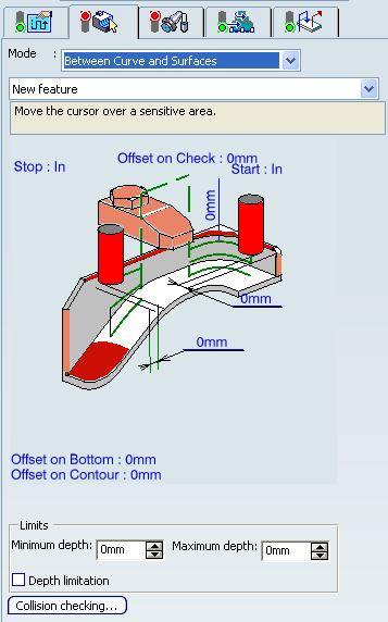
- Start and Stop relimiting elements with possible Offsets.
The In/On/Out setting allows you to specify the Go-Go type positioning of the tool with respect to the end element.
- Check elements with possible Offset on Check.
- Bottom (planar face or surface) with possible Offset on Bottom. If a negative offset value is specified, it must be less than the tool corner radius value.
- Guide contour (edges or sketch) with possible radial Offset on Contour and Axial Offset. Axial Offset is only taken into account when more than one axial level is defined.
- Limits: You can restrict machining to a specific zone by specifying Minimum depth and Maximum depth values. The depths are taken from the top guiding contour. The Depth limitation check box must be selected in this case.
- Start and Stop relimiting elements with possible Offsets.
- Mode: By Flank Contouring
- The tool flank machines a vertical part surface while respecting user-defined
geometry limitations and machining strategy parameters. The options in the
Mode: By Flank Contouring dropdown combo box are as follows:
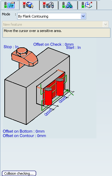
- Start and Stop relimiting elements with possible Offsets.
The In/On/Out setting allows you to specify the Go-Go type positioning of the tool with respect to the end element.
- Guiding flank (face parallel to tool axis) with possible Offset on Contour.
- Bottom with possible Offset on Bottom.
- Check elements with possible Offset on Check.
- Start and Stop relimiting elements with possible Offsets.
- Mode: Trim between curves and surfaces
- This mode is accessible only when a T-Slotter tool is selected and allows to machine the trimming tool (the surface defined at the machining operation level) with the upper section of the T-Slotter tool.The options in the
Mode: Trim between curves and surfaces dropdown combo box are as follows:
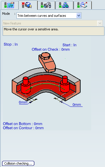
- Start and Stop relimiting elements with possible Offsets.
The In/On/Out setting allows you to specify the Go-Go type positioning of the tool with respect to the end element.
- Guide contour (edges or sketch) with possible Offset on Contour.
- Bottom with possible Offset on Bottom.
- Check elements with possible Offset on Check.
- Start and Stop relimiting elements with possible Offsets.
- Collision Checking
- Starts the Collision checking dialog box
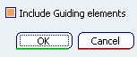
Collision checking is done during macro motions and machining motions (for corner and angle contouring). By default, all guiding elements defined on the operation are taken into account during this verification. However, in some cases, it can be useful to deactivate collision checking with the guides by clearing the Include Guiding elements in the dialog box. (see example below).- In the following figure, collision avoidance during the
circular approach macro is not necessary.
- In the following figure, there is no collision avoidance
during the circular approach.
- the check box is selected, guides are checked for collisions during macro motions and machining motions.
- When the check box is not selected, no collision verification is done with the guides for macro motions and for machining motions during tool plunges.
- In the specific case when there is no selected top element and no offset defined on the bottom element, there is no tool motion to avoid the guiding elements, so no collisions are detected (for macro motions only).
- In the following figure, collision avoidance during the
circular approach macro is not necessary.
![]()
Tools
Recommended tools for Profile Contouring are:
- End Mills
 ,
, - Face Mills
 ,
, - Conical
Mills
 , and
, and - T-Slotters
 .
. - Drills
 ,
, - Spot Drills
 ,
, - Center Drills
 , and
, and - Countersinks
 can also be used.
![]()
Feedrates and Speed Parameters
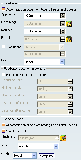
- Feedrate: Automatic compute from tooling Feeds and Speeds
- This check box allow an operation's feeds and speeds values to be updated automatically when the tool's feeds and speeds values are modified.
You can specify the following feedrates:
- Approach
- Machining
- Retract
- Finishing
Note:
The above feedrates can be defined in linear (feed per minute) or angular (feed per revolution) units.
- Angular: feedrate in revolutions per minute and unit is set to mm_turn.
- Linear: feedrate in feed per minute and unit is set to mm_mn.
- Transition
- You can locally set the feedrate for a transition path to a
machining operation B from a machining operation A or from a tool
change activity. This is done by selecting the Transition check box in the Machining Operation dialog box for
operation B.
For more information, please refer to the Setting a Transition Feedrate.
- Feedrate Reduction in Corners
- You can reduce feedrates in corners encountered along
the tool path depending on values given in the Feeds and Speeds
tab page for:
- Reduction rate
- Maximum radius
- Minimum angle
- Distance before corner
- Distance after corner
Feed reduction is applied to corners along the tool path whose radius is less than the Maximum radius value and whose arc angle is greater than the Minimum angle value.
For Profile Contouring, feedrate reduction applies to inside corners for machining or finishing passes. It does not apply for macros or default linking and return motions.
If a cornering is defined with a radius of 5mm and the feedrate reduction in corners set to a lower radius value, the feedrate cannot be reduced.
- Spindle Speed: Automatic compute from tooling Feeds and Speeds
This check box allow an operation's feeds and speeds values to be updated automatically when the tool's feeds and speeds values are modified.
If the Feedrate Automatic compute check box is selected and the Spindle Speed: Automatic compute from tooling Feeds and Speeds check box is not selected, then only the feedrate values can be computed. If both are not selected then automatic updating is not done.
When you modify a tool's feeds and speeds, all existing operations with the Automatic compute check boxes selected that use this tool (or an assembly using this tool) can be recomputed.
- Spindle output
- This check box manage output
of the SPINDL instruction in the generated NC data file:
- If the check box is selected, the instruction is generated.
- Otherwise, it is not generated.
Note:
The spindle speed can be defined in linear (length per minute) or angular (length per revolution) units.
- Angular: length in revolutions per minute and unit is set to mm_turn.
- Linear: length in feed per minute and unit is set to mm_mn.
- Quality
- The feed and speed values are computed according to the Quality setting on the operation.
- Compute
- Feeds and speeds of the operation can be updated according to tooling feeds and speeds by clicking the Compute button located in the Feeds and Speeds tab of the operation.
Feeds and speeds of the operation can be updated automatically according to tooling data and the rough or finish quality of the operation. This is described in About Feeds and Speeds.
![]()
NC Macros
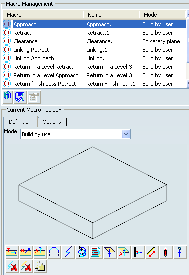
You can define transition paths in your machining operations by means
of NC macros. The selected macro type (Approach or Retract) defines the tool motion before
or after machining:
- Approach: to approach the operation start point.
- Retract: to retract from the operation end point.
- Linking: to link two non consecutive paths and to access finish and spring passes.
- Return between Levels to go to the next level in a multi-level machining operation.
- Return to Finish Pass to go to the finish pass.
- Clearance to avoid a fixture, for example.
The proposed macro mode are:
- None
- Build by user
- Circular horizontal axial
- Horizontal horizontal axial
- Axial
For more information, please refer to the Defining Macros.
Note: When a collision is detected between the tool and the part or a check element, a clearance macro is applied automatically. If applying a clearance macro would also result in a collision, then a linking macro is applied. In this case, the top plane defined in the operation is used in the linking macro. The top plane element must be selected in order to apply an automatic linking macro without collision.