Replaying the Tool Path | ||||||
|
| |||||
Select one or several Machining Operations, or a Manufacturing Program, then click Tool Path Replay
 . See About NC Manufacturing Verification.
- Optional: Click Cancel under the progress bar that appears to interrupt the computation.
- The Machining Operation tool path is computed interactively.
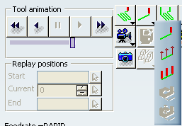
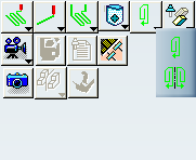
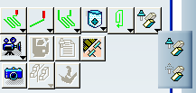
- The following dialog box appears at
the end of the computation. The name of the current
Machining Operation appears in the title bar.
- It contains icons for managing the Tool Path Replay and
material removal simulation and the following information:
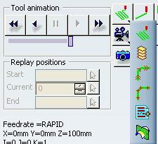
- the current feedrate.
- the current tool tip position (X, Y, Z) and tool axis orientation (I, J, K).
- the machining time and the total time.
the total time is machining time plus
non-machining time (i.e. time
spent in transition paths and so
on). These times are displayed in hh:mm:ss
format.
Note: Time values are always displayed rounded off to the nearest integer value and with no fractions displayed.
- The information (feed rate, tool path point and tool axis, machining and total time) displayed at the bottom of the Tool Path Replay dialog box, is consistent with the currently displayed tool path, even if it is a partial Tool Path Replay.
Select the desired replay mode:
 : displays the tool path continuously.
  : displays the tool path plane by plane. This is suitable
for multi-level operations such as Pocketing or Roughing.
: displays the tool path plane by plane. This is suitable
for multi-level operations such as Pocketing or Roughing.
- Consecutive portions of the tool path are displayed at each click on the forward (or backward) control button.
- All parts of the tool path on the same level may not be displayed together.
- Transition Paths may be displayed as you click forward (or backward).
- Approach and retract paths are displayed in a lower intensity.
-
 : displays the tool path feedrate by feedrate.
  : displays the tool path point by point.
 -
 : stops the Tool Path Replay each time a PP instruction is met. The syntax of the instruction is displayed on the trajectory
(for example, CYCLE/DRILL,0.000,1.000).
: stops the Tool Path Replay each time a PP instruction is met. The syntax of the instruction is displayed on the trajectory
(for example, CYCLE/DRILL,0.000,1.000). -
 : sections the tool path at each level. This mode is suitable for multi-level operations such
as Pocketing or Roughing.
: sections the tool path at each level. This mode is suitable for multi-level operations such
as Pocketing or Roughing.- A suitable direction is found to define the normal to the sectioning planes.
- The replay progresses level by level along this normal at each click on the forward (or backward) control button.
- All the portions of the tool path are displayed in a given sectioning plane.
You can choose to display the machined surface with or without the tool axes (see the Tool Visualization modes below).
Choose the desired color mode:
-
 :
displays the tool path in a single color.
:
displays the tool path in a single color.  By default,
this color is green.
By default,
this color is green.  :
displays the tool path in several colors, depending on the feedrates.
See Color Modes.
:
displays the tool path in several colors, depending on the feedrates.
See Color Modes.
-
For surface machining operations only, choose the desired point display mode:
 :
displays the trajectory of either the tool tip or the tool center
point.
:
displays the trajectory of either the tool tip or the tool center
point.  :
displays the trajectory of the contact point.
:
displays the trajectory of the contact point.  :
displays the trajectory of the contact point (if stored). Otherwise displays the trajectory of either the
tool tip or the tool center point.
:
displays the trajectory of the contact point (if stored). Otherwise displays the trajectory of either the
tool tip or the tool center point. :
displays the trajectories of the tool
tip or the tool center point and or the contact point (if stored).
:
displays the trajectories of the tool
tip or the tool center point and or the contact point (if stored).
Choose the desired TRACUT display mode:
 :
takes the TRACUT instructions into account to display
the tool path.
:
takes the TRACUT instructions into account to display
the tool path.-
 :
does not take the TRACUT instructions into account to display
the tool path.
:
does not take the TRACUT instructions into account to display
the tool path.
Choose the desired holder visibility option:
 :
displays the tool holder during the replay.
:
displays the tool holder during the replay. :
hides the tool holder during the replay. This option allows a better visibility when
checking the tool or tool path with respect
to the part. It can be used for default tool
assemblies and user representations.
:
hides the tool holder during the replay. This option allows a better visibility when
checking the tool or tool path with respect
to the part. It can be used for default tool
assemblies and user representations.
Control the Tool Path Replay using the following control buttons and keyboard shortcuts:
 or F5: positions the tool at the Machining Operation start
point.
or F5: positions the tool at the Machining Operation start
point. or F6: runs the replay backward.
 or F4: pauses the replay.
 or F7: runs the replay forward.
 or F8: goes to the Machining Operation end point.
- F7 or F6 kept pressed:
- for Point by Point, Plane by Plane, Feedrate by Feedrate, and Syntax by Syntax, replay steps are done continuously one after the other
- for Continuous, the animation speed increases at each refresh.
Note: You can customize the function keys to the replay buttons in the CATMfgReplayToolPathPanel.CATRsc resource file.
Optional: When replaying large tool paths, control the animation speed using the Tool animation speed slider:
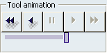
- In the first half of the slider, speed goes from one point to 10 points
- In the second half of the slider, speed goes from 10 points to N/10 (where N is the total number of points).
If required, select the Start, Current, and End Replay positions to perform a partial Tool Path Replay for the selected Machining Operation.
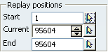
- Use the contextual menu to reset any replay position to its default value.
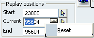
- The Start position is always less than the End position.
- The Current position specified must be between the Start and End positions.
- The End position cannot be greater than the last tool path position. In case of input position error, the last valid position is retained.
- If the Start and/or End positions are modified and are both higher/lower than the Current position, the current position is reset to the End position
- The Current and End positions displayed are based on the activity being replayed.
By default,
- the partial Tool Path Replay positions are always displayed.
- the Start position is the first point of the tool path
- the Current and End positions correspond to the last point on the tool path.
See Replay Tool Path
- Use the contextual menu to reset any replay position to its default value.