Selecting Guiding and Relimiting Elements | ||
| ||
Specify Guiding Contours
You can specify guiding contours in several ways.
-
Either
- Select
Contour detection in the bottom contextual menu
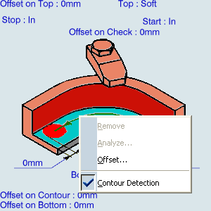
and select the bottom element. The boundary of the selected face is proposed as guiding contour. - or select edges. In this case the Selecting Edges and Faces to Define Geometry appears to help you specify the guiding contour.
- or select By Belt of Faces or By Boundary of Faces
in the guiding element contextual menu.
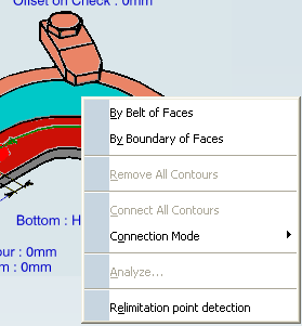
In this case the Selecting Edges and Faces to Define Geometry appears to help you specify the guiding contour.
- Select
Contour detection in the bottom contextual menu
![]()
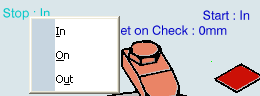
Specify Relimiting Elements
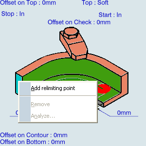
You can restrict the guiding contour with Start and Stop relimiting elements.
Once a guiding contour has been defined, right-click the relimiting element in the sensitive icon and select Add relimiting point.
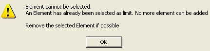
Note: More than one relimiting elements are not supported and if you select one relimiting element after another then a warning message appears.
If associativity with the part is not requested:
- Select points on the fly anywhere on the guiding contour.
- or select Relimitation point detection in the contextual menu.
Select a guiding contour, its extremities are used as relimiting elements.
Important: - Points created on the fly do not provide associativity with the part. Such points are only known via their XYZ coordinates. Since they are not part of the same Product as the part, V6 cannot ensure that their location is kept for each and any transformation applied to the part.
- Basic scenario where points are created on the fly on part1, then part1 is mounted on the machine once is supported. But an advanced scenario with several transformations (e.g. create the points on the fly on part1, mount part1, change part1 to part2, mount part2) is not supported. Create points on the fly only in a machining scenario where there is no move, nor change of the part.
Position the tool with regard to the Stop and Start relimiting elements.
![]()
Machine Discontinuous Guiding Curves
You can machine several discontinuous groups of guiding elements in all Profile Contouring modes (except By Flank Contouring).
Select the contours as explained above.
A Guide.x element is displayed for each selected continuous ordered contour.
- The side to mill is shown by the orange arrow.
- The order of in which the geometric elements are selected
determines the order in which they can be machined.
Once the selection of the guides is validated (that is, when the dialog box is displayed again), use the contextual menu that appears either on a guide in the authoring window or on a guide in the sensitive icon of the dialog box
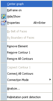
- Select Remove Element or launch the Edge Selection toolbar and pick an element again.
If the guide is no longer continuous, another guide is created.
- Before:
- After:
- Before:
- Select Remove Contour x
The selected contour is removed:.
- Before:
- After:
- Before:
- Select Remove All Contours
All contours are removed:.
- Before:
- After:
- Before:
- Select a contour, then Connect Contour X and the target contour
The first contour is connected to the target one.
- Before:
- After:
- Before:
- Select Connect All Contours
All contours are connected together.
- Before:
- After:
- Before:
- Select Remove Element or launch the Edge Selection toolbar and pick an element again.