Creating a Pocketing Operation for Open Pockets | |||||||
|
| ||||||
Activate the Manufacturing Program and click Pocketing
 in the Prismatic Machining Operation toolbar.
A Pocketing entity is added to the Manufacturing Program.
The Pocketing dialog box appears directly at the Geometry tab
 .
.The bottom and flanks of the icon are colored red indicating that this geometry is required for defining the pocket. All other pocket geometry is optional.
Still in the Geometry tab .
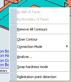
- Optional: Change all segments from Hard to Soft
and from Soft to Hard using the Swap Hardness Mode contextual
command.
- For parts containing islands, right-click the red
bottom in the icon and select Island Detection. This allows
island boundaries to be deduced automatically.
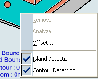
The pocket boundary is automatically deduced due to the Contour Detection setting. This is indicated by the highlighted drive elements.
Hard boundaries are shown by full lines and soft boundaries by dashed lines.
- Optional: Change all segments from Hard to Soft
and from Soft to Hard using the Swap Hardness Mode contextual
command.
Select the Strategy tab
 .
.- Choose the desired tool
path style: Inward helical, Outward helical or Back and forth.
- Choose the desired tool
path style: Inward helical, Outward helical or Back and forth.
Go to the Tool tab
 to select a tool.
Select the Feeds and Speeds tab
 to specify the feedrates
and spindle speeds for the operation.
to specify the feedrates
and spindle speeds for the operation. Select theMacros tab
 to specify the operation
transition paths. To specify approach motion:
to specify the operation
transition paths. To specify approach motion:See Defining Macros on Milling Operations
- In the Macro Management frame, right-click the Approach line and select the Activate contextual command.
- In the Current Macro Toolbox frame, select the Axial mode. An icon representing this approach motion is displayed.
- Double-click the distance parameter in the sensitive icon and enter the desired value in the pop-up dialog box.
- Repeat this procedure to specify retract motion.
Click Tool Path Replay
 to check the validity of the operation.
- The tool path is computed.
- A progress indicator is displayed.
- You can cancel the tool path computation at any moment before 100% completion.