Pocketing | |||||
| |||||
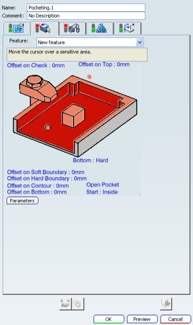
The Pocketing dialog box appears when you select Pocketing. This dialog box contains controls for:
Machining Strategy Parameters
- Tool Axis
- See Defining the Tool Axis
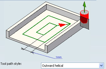
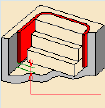
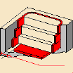
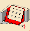
- Tool path style
- Specifies tool path style.
The options in the Tool path style dropdown combo box are as follows:
- Inward helical: the tool starts from a point inside the pocket and follows inward paths parallel to the boundary.
- Outward helical: the tool starts from a point inside the pocket and follows outward paths parallel to the boundary.
- Back and forth: the machining direction is reversed from one path to the next.
![]()
Machining Parameters
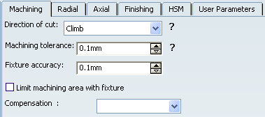
- Direction of cut
- Specifies how machining is to be done.
The options in the Direction of cut dropdown combo box are as follows:
- Climb milling: the front of the advancing tool (in the
machining direction) cuts into the material first
- Conventional milling: the rear of the advancing tool
(in the machining direction) cuts into the material first.
- Climb milling: the front of the advancing tool (in the
machining direction) cuts into the material first
- Machining tolerance
- Specifies the maximum allowed distance between the theoretical and computed tool path.
- Fixture accuracy
- Specifies a tolerance applied to the fixture thickness. If the distance between the tool and fixture is less than fixture thickness minus fixture accuracy, the position is eliminated from the trajectory. If the distance is greater, the position is not eliminated.
- Limit machining area with fixture
- Select this check box to re-limits the area to machine
for computing the tool path without jump motions around the check elements.
- Compensation
- Specifies the tool corrector identifier to be used in the operation. The corrector type (P1, P2, P3, for example), corrector identifier, and corrector number are defined on the tool. When the NC data source is generated, the corrector number can be generated using specific parameters.
![]()
Radial Parameters
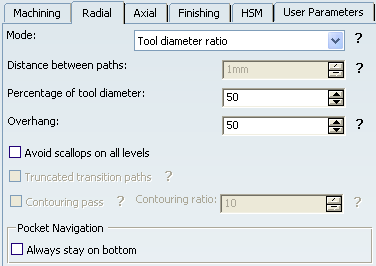
- Mode
The options in the Mode dropdown combo box specifies how the distance between two consecutive paths is computed, and are as follows:
- Maximum distance between paths
- Tool diameter ratio
- Stepover ratio
- Distance between paths
- Defines the maximum distance between two consecutive tool paths in a radial strategy.
- Percentage of tool diameter
-
Defines
the maximum distance between two consecutive tool paths in a radial strategy
as a percentage of the nominal tool diameter. Depending on the selected
radial mode, this value is used as:
- Tool diameter ratio:
- Stepover ratio:
- Tool diameter ratio:
- Overhang
- Allows a shift in the tool
position with respect to the soft boundary of the machining domain.
- Avoid scallops on all levels
- Select this check box to adjusts the
distance between paths to avoid
scallops on all level.
- Avoid scallops on all levels is not selected:
- Avoid scallops on all levels is selected:
- Avoid scallops on all levels is not selected:
- Truncated transition paths
- Contouring pass
- Select this check box to allows a final machining pass around the exterior of the trajectory and islands for removing scallops. This is available for Back and Forth tool path style.
- Contouring ratio
- Specifies the contouring ratio to adjust the position of the final contouring pass for removing scallops. This is done by entering a percentage of the tool diameter (0 to 50). This is available for Back and Forth tool path style.
- Always stay on bottom
- When machining a multi-domain pocket using a Helical tool path style, this parameter forces the tool to remain in contact with the pocket bottom when moving from one domain to another. This avoids unnecessary linking transitions.
![]()
Axial Parameters
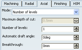
- Mode
The options in the Mode dropdown combo box specifies how the distance between two consecutive levels is computed, and are as follows:
- Maximum depth of cut
- Number of levels
- Number of levels without top
- Maximum depth of cut
- Defines the maximum depth of cut in an axial strategy.
- Number of levels
- Defines the number of levels to be machined in an axial strategy.
- Automatic draft angle
- Specifies the draft angle to be applied on the sides of the pocket.
- Breakthrough
- Specifies the distance in the tool axis direction that the tool must go completely through the part. Breakthrough is applied on the bottom element, which must be specified as soft.
![]()
Finishing Parameters
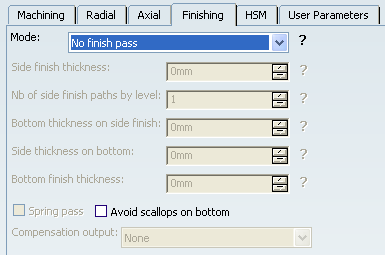
- Mode
The options in the Mode dropdown combo box specifies whether or not finish passes are generated on the sides and bottom of the area to machine, and are as follows:
- No finish pass
- Side finish last level
- Side finish each level
- Finish bottom only
- Side finish at each level & bottom
- Side finish at last level & bottom
In short:
- Side finishing can be done at each level or only at the last level of the operation.
- Bottom finishing can be done without any side finishing or with different combinations of side finishing.
- Side finish thickness
Specifies the thickness of material that can be machined by the side finish pass.- Number of side finish paths by level
- Specifies the number of side finish paths for each level in a multi-level
operation. This can help you to reduce the number of operations in the program.
- Bottom thickness on side finish
- Specifies the bottom thickness used for last side finish pass, if
side finishing is requested on the operation.
- Side thickness on bottom
Specifies the thickness of material left on the side by the bottom finish pass.- Bottom finish thickness
- Specifies the thickness of material that will be machined by the
bottom finish pass.
- Spring pass
- Select this check box to indicate whether or not a spring pass is to be generated on the sides in the same condition as the previous side finish pass. The spring pass is used to compensate the natural spring of the tool.
- Avoid scallops on bottom
- Select this check box to adjusts the distance between paths to avoid scallops on the bottom. This is available for single-level and multi-level operations with bottom finish pass.
- Compensation output
- The options in the
Compensation output dropdown combo box manage
the generation of Cutter compensation (CUTCOM) instructions for the pocketing
operation side finish pass, and are as follows:
- If 2D Radial profile is selected, both the tool tip and
cutter profile can be visualized during tool path replay. Cutter compensation
instructions are automatically generated in the NC data output. An approach
macro must be defined to allow the compensation to be applied.
Note: A negative Offset on contour (parameter in Geometry tab) is possible for 2D radial profile output.
- If 2D Radial tip is selected, the tool tip can be visualized during tool path replay. Cutter compensation instructions are automatically generated in the NC data output. An approach macro must be defined to allow the compensation to be applied.
- If None is selected, cutter compensation instructions are not automatically generated in the NC data output. However, CUTCOM instructions can be inserted manually. In this case, refer to Procedure for Generating CUTCOM Syntaxes.
Note: The PP words in macros you define are added to the cutter compensation instructions generated in the NC data output. Therefore be careful when specifying CUTCOM instructions in macros.
- If 2D Radial profile is selected, both the tool tip and
cutter profile can be visualized during tool path replay. Cutter compensation
instructions are automatically generated in the NC data output. An approach
macro must be defined to allow the compensation to be applied.
![]()
HSM Parameters

- High Speed Milling
- Specifies whether or not cornering for HSM is to be done on the trajectory.
- Corner radius
- Specifies the radius
used for rounding the corners along the trajectory of a HSM operation. Value
must be smaller than the tool radius.
- Limit angle
- Specifies the minimum angle
for rounding corners in the tool path for a HSM operation.
- Extra segment overlap
- Specifies the
overlap for the extra segments that are generated for cornering in a HSM
operation. This is to ensure that there is no leftover material in the corners
of the trajectory.
- Cornering on side finish path
- Specifies whether or not tool path cornering is to be done on side finish path.
- Corner radius on side finish path
- Specifies the radius used for rounding the corners of the side finish path in a HSM operation. Value must be smaller than the tool radius.
- Limit angle on side finish path
- Specifies the minimum angle for rounding the corners of the side finish path in a HSM operation.
- Transition radius
- Specifies the radius at the start and end of the transition path when moving
from one path to the next in a HSM operation.
- Transition angle
-
Specifies the angle of the transition path that allows the tool to move
smoothly from one path to the next in a HSM operation.
- Transition length
- Specifies a minimum length for the straight segment of the transition between
paths in a HSM operation.
![]()
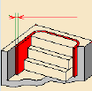
Geometry
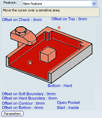
You can specify the following geometry:
- Pocket Bottom (planar face or surface) with possible Offset on Bottom. Bottom may be Hard or Soft.
- Pocket Boundary (edges or sketch) with possible:
- Offset on Hard Boundary,
- Offset on Soft Boundary,
- Offset on Contour. If you specify an Offset on Contour, it is added to any defined Offset on Hard Boundary,Offset on Soft Boundary, and Offset on Island.
- Pocket Top plane with possible Offset on Top.
- Islands (defined by hard boundaries) with possible offset on each island.
- Check elements with possible Offset on Check.
- Start point and End point as preferential start
and end positions for the operation. This allows a better control for optimizing
the program according to the previous and following operations.
Note: The Start point can be located outside an open pocket. In this case, you must specify a clearance with respect to the pocket boundary.
 ,
, ,
, , and
, and .
.![]()
Feedrates and Speeds Parameters
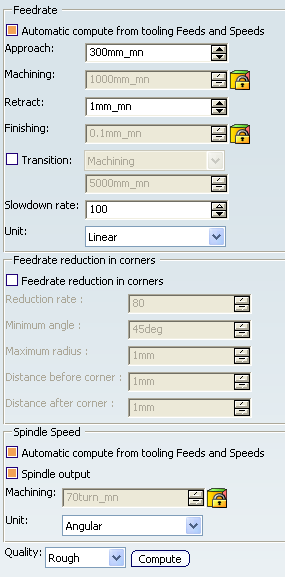
- Feedrate: Automatic compute from tooling Feeds and Speeds
- This check box allow an operation's feeds and speeds values to be updated automatically when the tool's feeds and speeds values are modified.
You can specify the following feedrates:
- Approach
- Machining
- Retract
- Finishing
Note:
The above feedrates can be defined in linear (feed per minute) or angular (feed per revolution) units.
- Angular: feedrate in revolutions per minute and unit is set to mm_turn.
- Linear: feedrate in feed per minute and unit is set to mm_mn.
- Transition
- You can locally set the feedrate for a transition path to a
machining operation B from a machining operation A or from a tool
change activity. This is done by selecting the Transition check box in the Machining Operation dialog box for
operation B.
For more information, please refer to the Setting a Transition Feedrate.
- Slowdown Rate
- Reduces the current feedrate by a given percentage. The reduction is applied to the first channel cut and to the transitions between passes.
- Feedrate Reduction in Corners
- You can reduce feedrates in corners encountered along
the tool path depending on values given in the Feeds and Speeds
tab page:
- Reduction rate
- Maximum radius
- Minimum angle
- Distance before corner
- Distance after corner
Feed reduction is applied to corners along the tool path whose radius is less than the Maximum radius value and whose arc angle is greater than the Minimum angle value.
For Pocketing, feedrate reduction applies to machining and finishing passes:
- for all corners in Back and forth mode
- for inside corners in Inward and Outward Helical mode.
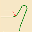
- The figure below shows that feedrate reduction is not applied in Inward
Helical for most of the corners, as these are not inside corners.
- The figure below shows that feedrate reduction is applied in each corner
in Outward Helical, as these are inside corners.
Feedrate reduction does not apply for macros or default linking and return motions.
Corners can be angled or rounded, and may include extra segments for HSM operations.
- Combining Slowdown Rate and Feedrate Reduction in Corners
If a corner is included in a slowdown path, the general rule is that the lowest percentage value is taken into account. For example:
- if the Slowdown rate is set to 70 % and Feedrate reduction rate in corners is set to 50%, the feedrate sequence is: 100%, 70% (entry in slowdown), 50% (entry in corner), 70% (end of corner, still in slowdown), 100% (end of slowdown).
- If feedrate Reduction rate in corners is then set to 75%, the feedrate sequence is: 100%, 70% (entry in slowdown), 70% (entry in corner: 75% ignored), 70% (end of corner, still in slowdown), 100% (end of slowdown).
- Spindle Speed: Automatic compute from tooling Feeds and Speeds
This check box allow an operation's feeds and speeds values to be updated automatically when the tool's feeds and speeds values are modified.
If the Feedrate Automatic compute check box is selected and the Spindle Speed: Automatic compute from tooling Feeds and Speeds check box is not selected, then only the feedrate values can be computed. If both are not selected then automatic updating is not done.
When you modify a tool's feeds and speeds, all existing operations with the Automatic compute check boxes selected that use this tool (or an assembly using this tool) can be recomputed.
- Spindle output
- This check box manage output
of the SPINDL instruction in the generated NC data file:
- If the check box is selected, the instruction is generated.
- Otherwise, it is not generated.
Note:
The spindle speed can be defined in linear (length per minute) or angular (length per revolution) units.
- Angular: length in revolutions per minute and unit is set to mm_turn.
- Linear: length in feed per minute and unit is set to mm_mn.
- Quality
- The feed and speed values are computed according to the Quality setting on the operation.
- Compute
- Feeds and speeds of the operation can be updated according to tooling feeds and speeds by clicking the Compute button located in the Feeds and Speeds tab of the operation.
Feeds and speeds of the operation can be updated automatically according to tooling data and the Rough or Finish quality of the operation. This is described in About Feeds and Speeds.
![]()
NC Macros
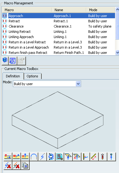
You can define transition paths in your machining operations by means
of NC macros:
- Approach: to approach the operation start point,
- Retract: to retract from the operation end point,
- Linking: to link motions in the tool path,
- Return between Levels to go to the next level in a multi-level machining operation,
- Return to Finish Pass to go to the finish pass
- Clearance to avoid a fixture, for example.
When a collision is detected between the tool and the part or a check element, a clearance macro is applied automatically. If applying a clearance macro would also result in a collision, then a linking macro is applied. In this case, the top plane defined in the operation is used in the linking macro.
The proposed macro mode are:
- None
- Build by user
- Horizontal horizontal axial
- Axial
- Ramping
For more information, please refer to the Defining Macros.
- Intermediate Levels
Right-click Parameters in the contextual menu of a Ramping approach macro mode.
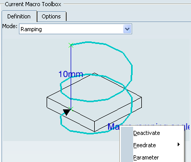
The following dialog box appears:
When Intermediate levels check box is selected, the approach macro is divided in three parts:- A ramping approach from the top of the pocket to the intermediate level
- A horizontal path, which is the same as the first path if the machining mode is Back and Forth or the first closed path if the machining mode is Helical
- A ramping approach from the intermediate level to the machining level.
The yellow path in the figure below illustrates an intermediate level for a ramping approach macro in a Back and Forth Pocketing operation.