Procedure for Generating CUTCOM Syntaxes | ||||||
|
| |||||
Select the Compensation Output Option
The Compensation output allows you to manage the generation of CUTCOM instructions in the NC data output.
- Go to the Strategy tab of the machining
operation and set Compensation output to None.
The other options are:
- 2D Radial profile: both the tool tip and cutter profile are visualized during tool path replay. Cutter compensation instructions are automatically generated in the NC data output. An approach macro must be defined to allow the compensation to be applied.
- 2D Radial tip: the tool tip is visualized during tool path replay. Cutter compensation instructions are automatically generated in the NC data output. An approach macro must be defined to allow the compensation to be applied.
With None, the cutter compensation instructions are not generated automatically in the NC data output. The procedure below describes how to manage the cutter compensation manually.
![]()
Select Position in Macro for Cutter Compensation
This procedure describes you how to select a position in macro for cutter compensation
-
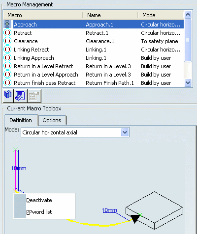
Go to the Macro tab
 of the
machining operation
dialog box.
See Defining Macros
![]()
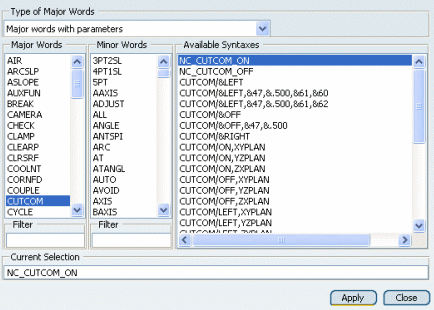
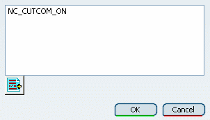
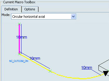
Insert CUTCOM PP Word in the Macro
This procedure describes you how to insert customized PP word in macro tool path.
![]()
Complete the Machining Operation Definition
Define the other parameters of the operation (geometry, tool, and machining strategy).
- Click OK to validate the machining operation and exit the dialog box.
Generated APT Source
Here is an example of the type of APT source that can be obtained for a Profile Contouring operation when a NC_CUTCOM_ON word was inserted in the approach macro and a NC_CUTCOM_OFF word was inserted in the retract macro.
$$Start generation of:Profile Contouring.1 FEDRAT/ 300.0000,MMPM SPINDL/ 500.0000,SFM,CLW |
|
GOTO/-110.00000, 80.00000, 10.00000 GOTO/-110.00000, 80.00000, 0.00000 CUTCOM/LEFT GOTO/-110.00000, 70.00000, 0.00000 INTOL/0.10000 OUTTOL/0.00000 AUTOPS INDIRV/0.00000, -1.00000, 0.00000 TLON,GOFWD(CIRCLE/-100.00000, 70.00000,0.00000,$ 10.00000),ON,(LINE/-100.00000, 70.00000,0.00000,$ -100.00000, 60.00000, 0.00000) |
Approach macro: NC_CUTCOM_ON is generated as CUTCOM/LEFT |
FEDRAT/ 1000.0000,MMPM GOTO / 100.00000, 60.00000, 0.00000 INDIRV/ 1.00000, 0.00000, 0.00000 TLON,GOFWD/ (CIRCLE/ 100.00000, 50.00000, 0.00000,$ 10.00000),ON,(LINE/ 100.00000, 50.00000, 0.00000,$ 110.00000, 50.00000, 0.00000) GOTO / 110.00000, -50.00000 |
|
FEDRAT/200.0000,MMPM INDIRV/0.00000, -1.00000, 0.00000 TLON,GOFWD(CIRCLE/120.00000, -50.00000,0.00000,$ 10.00000),ON,(LINE/120.00000, -50.00000,0.00000,$ 120.00000, -60.00000, 0.00000) CUTCOM/OFF GOTO/130.00000, -60.00000, 0.00000 GOTO/ 30.00000, -60.00000, 10.00000 |
Retract macro: NC_CUTCOM_OFF is generated as CUTCOM/OFF |


