Creating Rectangular Patterns | |||
| |||
Duplicate a Pocket
You can create rectangular pattern by maintaining equal spacing between the instances.
Select the feature you want to copy. For the purpose of our scenario, select the pocket.
Important: You cannot pattern wireframe, surface, and volume elements. 
Click Rectangular Pattern
 in the Transformation Features toolbar (Patterns sub-toolbar).
The Rectangular Pattern Definition dialog box that appears displays the name of the geometry to pattern. Each tab is dedicated to a direction you will use to define the location of the duplicated feature.
Important: - If you click
Rectangular Pattern
before selecting any geometry, by default, the object to be patterned
is the current solid. For more information, see
Patterning Current Solids.
- If you change your mind and decide to pattern the current solid, click the Object box and use the Get current solid contextual command.
- If you click
Rectangular Pattern
In this task, you will first set your specifications for the first direction. In the Reference element box, select the edge as shown below to specify the first direction of creation.
An arrow is displayed on the pad. If needed, click the Reverse button or click the arrow to modify the direction.
In the Spacing box, type 14 mm to define the spacing along the grid.
Keep Instance(s) & Spacing and enter 3 and 10 mm in the appropriate box.
Click Preview to make sure the pattern meets your needs.
Additional pockets will be aligned along this second direction.
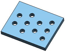
Click OK to repeat the pocket's geometry nine times.
This is the resulting pattern. The RectPattern.1 feature is displayed in the specification tree.
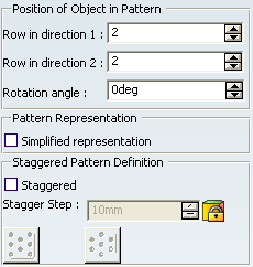
Click More >> to display the whole dialog box.
The options available let you position the pattern.
Click Preview.
You can notice that all the pockets have moved slightly:
In the Row in direction 1 box, type 2 to modify the location of the initial pocket.
The application previews how the pattern will be moved. It will be moved along the direction as indicated:
In the Row in Direction 2 box, type 2.
The application previews how the pattern will be moved. It will be moved along these two directions defined in steps 17 and 18:
Click OK.
The application has changed the location of all pockets. Only four of them remain on the pad.
![]()
Specify Specific Spacing Values between Each Instance
You can assign specific spacing values between each instance.
Select the pocket as the object to pattern, and first set the Instance(s) & Length parameter using the length values as shown here:
To edit the values between each instance, you need to edit values individually. First, select the spacing of interest if not already done.
Choose one of the methods described hereafter: For example, if you want to change 10mm for 17mm for the selected spacing, you can:
- Double-click the length value in the geometry area. This displays the Parameter Definition dialog box in which you can enter the new value.
- Directly enter the new value in the Spacing box of the Rectangular Pattern Definition dialog box.
![]()
Create a Staggered Pattern
You can create the specific staggered pattern configurations by offsetting the alternate rows of the pattern by certain distance.
Create a rectangular pattern as shown below:
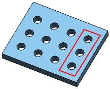
Note: The reference row is marked in the red color.
Select the Staggered check box in the Staggered Pattern Definition area.
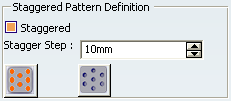
By default, the
 option is selected to keep the number of instances in the
reference row more than its adjacent row.
option is selected to keep the number of instances in the
reference row more than its adjacent row.Note: You can click
 to keep the number of instances in the reference row less than its adjacent row.
Click OK.
The staggered pattern is created.