Choose Between Reference Parameters and Local Modifications
You can choose to propagate the reference parameters of the machine in the Generic Machine dialog box or allow local modifications in the Local Modifications dialog box of the Machine Configuration View.
The steps below describe the behavior in the Generic Machine dialog box.
Machines are created either using
the Machine Tool Builder product or on the fly in Machine Programming as PLM objects. Then the machine is instantiated under the Machining Cell. The Generic Machine dialog box shows parameters of the
reference. The parameters of instance are available in the Local Modifications dialog box of the Machine Configuration View.:
- Editing these parameters requires
propagating the machine resource.
- Most reference parameters that are available in Generic Machine dialog box are also available in the Local Modifications dialog box. However:
- for Mill Turn machines, the turret and spindle parameters
are only available on the reference machine, the corresponding
tabs
are not available in Local Modifications,
To edit a machine parameters, either:
- double-click the machine in the PPR Context,
- double-click the machine in the Machine Configuration View,
- or right-click the machine in the PPR Context and select Edit in the contextual menu.
The Generic Machine dialog box is displayed.
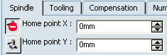
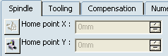
In Generic Machine dialog box, allow or forbid access to the Local Modifications machine parameters in Machine Configuration View. - Click
 in front of a parameter. in front of a parameter. It changes to  , meaning the parameter is not editable in Local Modifications. For example: , meaning the parameter is not editable in Local Modifications. For example:
- Reference paramaetrs In Generic Machine dialog box:
- Local Modifications in Machine Configuration View:
- Click again to revert to the original edition status.
Regarding Local Modifications parameters, by default, they are all disabled and are similar to the Generic Machine dialog box parameters. - When possible, click in front of the parameter.
It changes to  , the parameter becomes editable, enabling you to modify the parameter locally in the context of Machining Cell (instance parameters). , the parameter becomes editable, enabling you to modify the parameter locally in the context of Machining Cell (instance parameters).
- Click again to reset the
parameter.
- Click Reset Local Modifications to reset all
local modification parameters.
Go either to Generic Machine dialog box parameters or Machine Configuration local parameters to edit the required parameters.

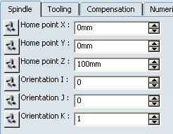
Edit the Spindle Parameters
You can edit spindle parameters for all machines.
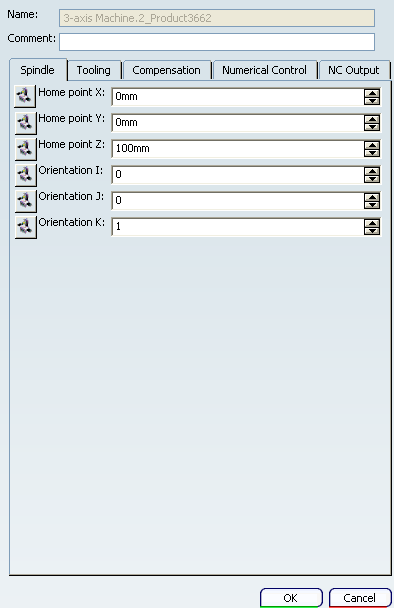
Go to the Spindle tab. For the Mill-Turn Machine
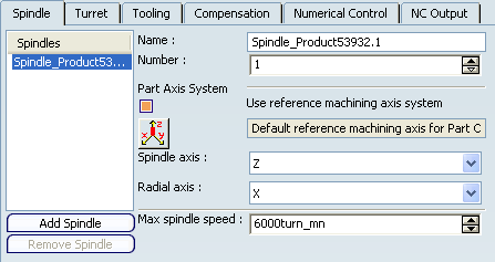
See Multi-slide Lathe Machining: Programming for Multi-Spindle Lathe
Machining: Setting Up Environment for Multi-Spindle Machining and About Machines. For other machines, edit the Home point and the Orientation.
Note:
When an Machining Operation is edited, its associated spindle and
corresponding spindle axis system is highlighted in the authoring window.
Edit the Turret Parameters
You can edit the Turret parameters for Mill-Turn machines.
- Go to the Turret tab.
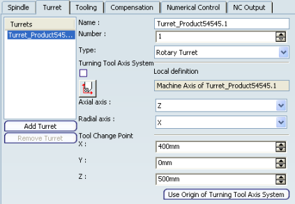
See Multi-slide Lathe Machining: Programming for Multi-Spindle Lathe
Machining: Setting Up Environment for Multi-Spindle Machining and About Machines. Note:
When a Manufacturing Program is
edited, its associated turret and corresponding turret axis system
are highlighted in the authoring window.
Edit the Rotary Table Parameters
You can edit Rotary Table parameters for 3-axis machines with rotary table.
Go to the Rotary Table tab.
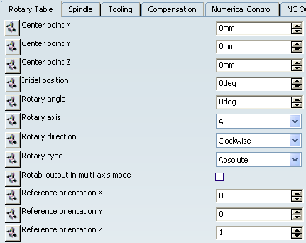
Select the Rotary axis from the list (A, B, C). Select the Rotary direction from the list (Clockwise, Counter-clockwise, Shortest). Select the Rotary type from the list (Absolute is currently the only possible value). Select the Rotabl output in multi-axis mode, if required.  By default,
this check box is not selected.
By default,
this check box is not selected.
Edit the other values as required.
Edit the Compensation Parameters
You can edit the Compensation parameters for all machines.
Go to the Compensation tab.
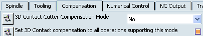
Select the 3D Contact
Compensation Mode from the list (No, Contact, Tip & Contact) Select the check box Set 3D Contact compensation to all operations supporting this mode.
- This check box can only be selected when 3D Contact
Compensation Mode is set to No.
- Some Machining Operations
propose cutter compensation modes other than 3D contact
(2D radial profile, for example). See About Machines for more information.
If Set 3D Contact compensation to all operations supporting this mode is not selected and 3D Contact
Compensation Mode is set to Contact or the
Tip & Contact, a Compensation
tab appears in the Strategy page of the Machining Operation
editor. In this case, 3D contact compensation
can be managed at the Machining Operation level.
Edit the Numerical Control Parameters
You can edit Numerical Control parameters for all machines.
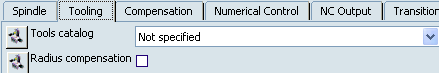
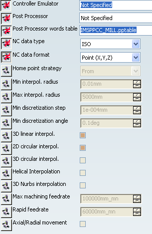
Go to the Numerical Control tab.
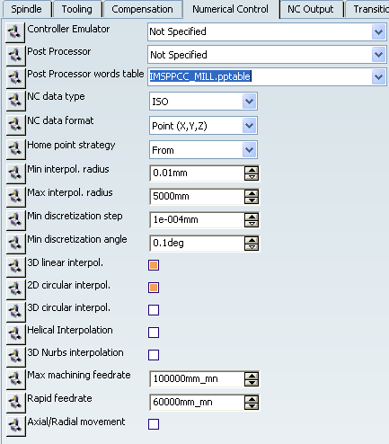
Select the desired Controller Emulator and Post Processor from the alphanumerically
ordered lists of available emulators and PPs. Note:
- The Controller Emulator parameter appears only for MillTurn machine.
- A Controller Emulator/Post Processor vendor
must be set in . See Output for more information.
Select the desired Post Processor words table from the alphanumerically
ordered list of available PP word tables. Note:
- The PP word tables are specified in .
-
Sample PP word tables are delivered in the ..\startup\manufacturing\PPTables folder.
- See Resources for more information.
Select the preferred
NC Data Type: - APT: Specifies
APT source output.
- CLF-3000 or
CLF-15000: Specifies Clfile output.
In case of circular interpolation, either 3000
and 5000 record type clfiles or 15000 record
type clfiles are generated.
- ISO: Specifies
NC code output.
Select the preferred NC data format - Point: tool point coordinates (x,y,z)
- Axis: tool axis components
(x,y,z,i,j,k)
Select the Home
point strategy (i.e. whether a GOTO or FROM instruction is generated in the output APT source for the home point) from the list (FROM or GOTO). See NC Data Options for more information. Define the Min interpol. radius and the Max interpol. radius used in the tool path computation
and output file generation when generating circular
interpolation. Check and possibly modify
these values before creating a Machining Operation.
Otherwise, correct circular interpolation
may not appear in the NC data output. - If an interpolation value
is modified after the creation of the Machining Operation and
the generation of the tool path, re-compute the tool paths
before generating the output file.
Select the Min discretization step and Min discretization angle. Specify the ability to make: - a 3D linear interpolation
between 2 points.
- a 2D circular interpolation
between 2 points.
- a 3D circular interpolation
between 2 points.
- a Helical Interpolation
between two consecutive points
Specify
the ability to generate 3D NURBS interpolation data in
an APT output file. See NURBS Formats in APT Output for more information.
- When this check box is selected, an Output tab
is available in the Machining Operation
dialog box (for all those Machining Operations that
support NURBS).
- If the Nurbs format checkbox
in the Output tab is selected, NURBS
output data is generated for the Machining Operation.
- If it is not selected, there is no NURBS output data generated for the Machining Operation.
Specify the Maximum Machining Feedrate. Specify the Rapid feedrate. This is used to compute an accurate machining time
(inTool Path Replay, for example) and can be used
to replace the RAPID instruction in the output APT
source. Refer to NC Data Options
for more information. Specify whether Axial/radial movement are to
be used between the end of one Machining Operation and the
start of the next one.
A RAPID GOTO statement is added for the
axial-radial movement if the option is selected.
Edit NC Output Parameters
You can define NC Output parameters for all machines.
Go to the NC Output tab.
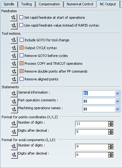
Specify the required options for - Feedrates
- Tool motions
- Statements (for example, general
information statements to be presented with the
PPRINT syntax)
- Format for point coordinates
(X,Y,Z) and Format for axial components (I,J,K).
See
NC Data Options for more information.
Edit the Transition Path Parameters
You can edit the Transition Path parameters once a physical machine has been selected.
Go to the Transition Path tab.
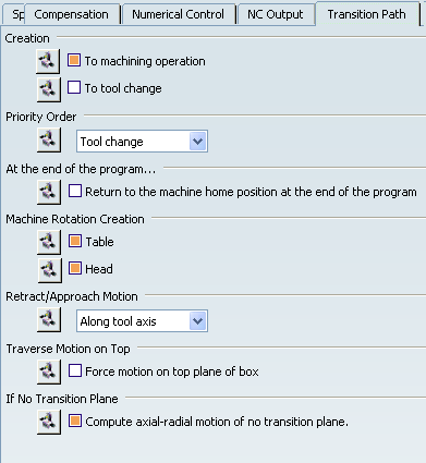
Specify where you want to add a Transition Path in the Manufacturing Program: - To Machining Operation: Transition Paths are generated before each Machining Operation. If there is a machining axis before a Machining Operation, the Transition Path is added before the machining axis.
- To Tool Change: Transition Paths are added before each Tool Change.
- None: Transition Paths cannot be created.
Specify the preferred order between Tool Change and Machine Rotation when they are both present before a Machining Operation. - Tool Change: The Machine Rotation is embedded in the Transition Path that is after the Tool Change.
- Machine Rotation: The Machine Rotation is embedded in the Transition Path that is before the Tool Change.
Select the check box Return to the machine home position at the end of the program to generate an additional Transition Path after the last Machining Operation in order to return to the machine home position. Select the check boxes in Machine Rotation Creation to allow creation of a rotary motion embedded in the Transition Path with the generation of Machine Rotation instructions in the output file (for example, ROTABL and ROTHED) and automatic checking of machine reachability for rotary motion. If Table is selected, and if a table rotation is
needed, the tool retracts to the specified rotary plane and makes
the table rotation. A head rotation is also done if necessary. Specify how Retract/Approach Motions are to be done globally for all the Transition Paths of all selected Manufacturing Programs. - Normal to transition plane
- Along tool axis
If a specific retract or approach is required on a Machining Operation, define it by macros on the Machining Operation. Select the check box Force motion on top plane of box. It is useful when a Transition Path needs to go from one side to the opposite side of the traverse box.
- This option is taken into account only when all five traverse planes are defined in the Part Operation.
- The intermediate plane can be any one of the three other planes.
- If the check box is selected, the top plane is used as the intermediate plane.
- Otherwise, the motion can be done using the intermediate plane that gives the shortest path.
Select the check box Compute axial-radial motion of no transition plane Tool axis direction at start and end of motion must be the same. If a traverse box is not defined, and if no transition plane is selected, selecting this check box authorizes 2.5 axis motion only.
Exit the Generic Machine Editor
You must validate your changes when done.
- Click OK in the Generic Machine dialog box to validate
any modified parameter and assign the machine to the
Machining Cell.
|