Creating a Machine Configuration View | ||||
|
| |||
From any Product:
- Alternatively, open an existing Machining Process or PPR context .
 By default,
the
Activities Process Tree opens
automatically.
By default,
the
Activities Process Tree opens
automatically.
- Alternatively, open an existing Machining Process or PPR context .
Select Machine Configuration View
 in the top left toolbar.
The Machine Configuration View is displayed.
Click
 Insert Machine Accessories to insert machine accessories.
It is equivalent to the Machining Cell contextual menu items .
- In the Select Machine Accessories to insert dialog box that appears, search and select the required machine accessory from the database.
The Machine Configuration View is updated with the new inserted machine accessory.
Click
 Insert Tool Assemblies to insert tool assemblies.
It is equivalent to the Machining Cell contextual menu items .
- In the Select Tool Assemblies to insert dialog box that appears, search and select the required tool assembly from the database.
To mount and unmount accessories and adapters:
An adapter is a machine accessory with base mount port and one or several tool mount ports. It can be instantiated in Machining Cell and is simulated like any other machine accessory.
The accessories and adapters selected in the Machine Configuration View are highlighted in the authoring window.
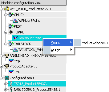
- Right-click a tool mount point and select available accessories to mount.
- Right-click a tool mount point and select available adapters to mount.
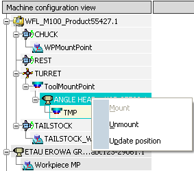
- Right-click mounted accessories or adapters and select Unmount to unmount the accessories or adapters.
- Right-click a tool mount point and select available accessories to mount.
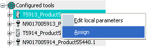
To assign and un-assign tool assemblies:
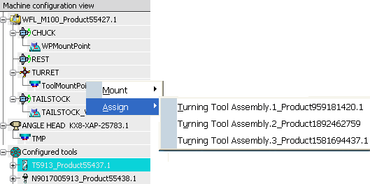
- Right-click a tool mount point and select Assign to assign tool assemblies.
- Click Turning Tool Change
 in the Activities Process Tree to open the Turning Tool Change dialog box.
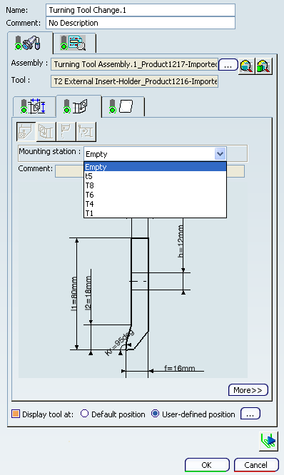
The Mounting station displays all the available free tool mount ports of turrets and of mounted adapters.
- Right-click a tool mount point and select Assign to assign tool assemblies.
To mount adapters or accessories in the authoring window:
- Right-click adapters or accessories in Machine Configuration View and select Mount.
The message appears asking you to select an axis system in the authoring window.
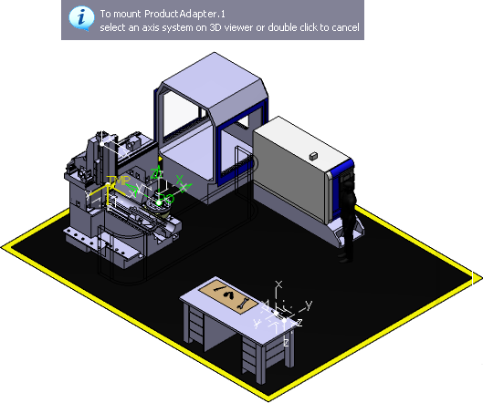
- Right-click adapters or accessories in Machine Configuration View and select Mount.
To assign tools in the authoring window:
- Right-click a tool in Machine Configuration View and select Assign.
The message appears asking you to select an axis system in the authoring window.
- Right-click a tool in Machine Configuration View and select Assign.
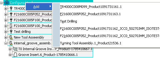
To edit and manage tool configuration parameter:
Tool configuration parameter are defined locally in the Machining Cell and not in the tool, like tool compensation, tool number, etc. The tool parameter is instantiated when a tool is assigned to a Machining Cell.
- Right-click Configured tools and select Add to add Turning Tool Assembly.
This instantiate tool parameter on a new tool assembly or tool (aggregated under Machining Cell).
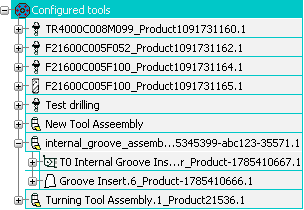
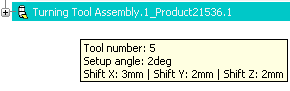
- Place mouse cursor on tool assembly to display tooltip.
The tooltip display value of tool configuration parameter.
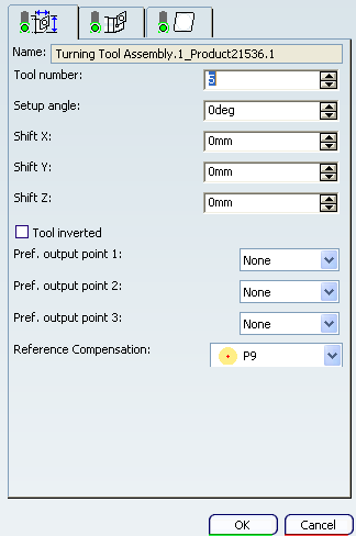
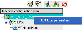
- Right-click a tool assembly and select Edit Local Parameters
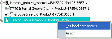
The Turning Tool Assembly dialog box is displayed.
- Right-click Configured tools and select Add to add Turning Tool Assembly.
Click
 Assign Machine from Database to assign a machine from database.
It is equivalent to the Machining Cell contextual menu item .
- In the Machine Selection dialog box that appears, search and select the required configured Machine from the database.
- If configuration information already exist in the Machining Cell, decide to replace them or not.
The machine configuration is assigned to the current Machining Cell.
Click
 Load Predefined Configuration to load a predefined configuration.
- In the Select Configured Machining Cell dialog box that appears, search and select the required configured Machining Cell from the database.
- If configuration information already exist in the Machining Cell, decide to replace them or not.
The predefined machine configuration is assigned to the current Machining Cell.
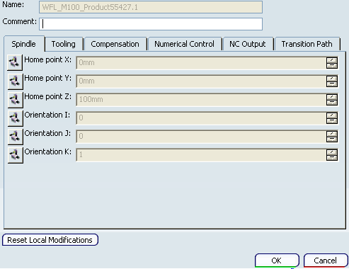
Right-click a Machining Cell and select Edit Local Parameters.
Modify the machine parameters in the Local Modifications dialog box.
Click
 Update Positions to update the position of accessories, adapters, tool, and setup assemblies.
 This is equivalent to the Machining Cell contextual menu item
The positions of the accessories are updated.