About Machines | ||||
|
| |||
Working with Machines
This section provides information about machine parameters, selecting a machine from database, and Machining Operations supporting circular interpolation and cutter compensation.
Machining Operations with Cutter Compensation
You can set cutter compensation options in the Compensation tab of the Generic Machine dialog box .
Cutter compensation instructions are generated on the NC data output depending on the selected mode as follows:
- 2D radial tip
- Compensation is computed in a plane normal to the tool axis, and activated with regard to a cutter side (left or right). The radius that is compensated is the cutter radius. Output is the tool tip point (XT).
- 2D radial profile
- Compensation is computed in a plane normal to the tool axis, and activated with regard to a cutter side (left or right). The radius that is compensated is the cutter radius. Output is the tool profile point (XP).
- 3D radial
- Compensation is computed along a 3D vector (PQR), normal to the drive surface, in contact with the flank of the tool. The radius that is compensated is the cutter radius. Output is the tool tip point (XT) and PQR vector. Tool axis vector (IJK) is output in multi-axis.
- 3D contact
- Compensation is computed along a 3D vector (XN), normal to the part surface, in contact with the end of the tool. The radius that is compensated is the corner radius. Output is the contact point (XC) and XN vector. The tool tip point (XT) may also be given if this choice is set on the machine. Tool axis vector (IJK) is output in multi-axis.
The table below specifies the compensation output modes available for each operation.
| Machining Operation | 2D Radial Tip | 2D Radial Profile | 3D Radial | 3D Contact |
|---|---|---|---|---|
| Profile Contouring (between planes) | Yes | Yes | - | - |
| Pocketing | Yes | Yes | - | - |
| Circular Milling | Yes | Yes | - | - |
| Sweeping | - | - | - | Yes(*) |
| Contour Driven | - | - | - | Yes(*) |
| Spiral Milling | - | - | - | Yes(*) |
| ZLevel | - | - | - | Yes(*) |
| Isoparametric Machining | - | - | - | Yes |
| Multi-Axis Sweeping | - | - | - | Yes |
| Multi-Axis Curve (Contact) | - | - | - | Yes |
| Multi-Axis Contour Driven | - | - | - | Yes |
| Multi-Axis Helix Machining | - | - | - | Yes |
| Multi-Axis Flank Contouring | - | Yes | Yes | - |
(*) In this release, only available when Offset Group with Offset Area is not used.
Machining Operations Supporting Circular Interpolation
Machining Operations supporting
circular interpolation are:
- Roughing, Cavities Roughing, Multi-Pockets Machining:
only when the Tool path style is set to Spiral, Concentric, Helical,
or Offset from Part.
Note: contouring passes do not support circular interpolation.
- Zlevel: only for circular macros.
- Facing, Pocketing, Profile Contouring, Curve Following, and Groove Milling.
- Circular Milling, Thread Milling (for circular macros), and T-Slotting.
- Multi-Axis Curve Machining.
- Circular macros of all Machining Operations but only for planar trajectories.
![]()
3D Feature for Spindles and Turrets
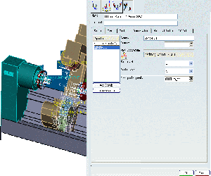
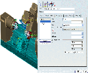
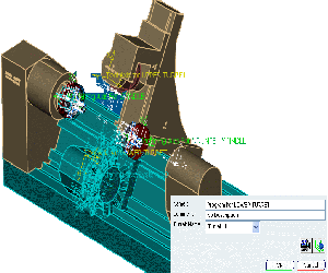
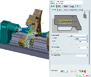
When the spindle/turret item is selected in the spindle/turret tab of the , the corresponding spindle/turret and the associated spindle/turret axis system is highlighted in the authoring window.
3D Feature for Spindles
When the spindle is selected in the spindle list of Spindle
tab of the , the corresponding spindle and the
associated spindle axis system are highlighted in the authoring window.
3D Feature for Turrets
When the turret is selected in the turret list of Turret tab
of the , the corresponding turret and the
associated turret axis system are highlighted in the authoring window.
This can be applicable for mill turret also.

