Creating a Machining Operation | ||||||
|
| |||||
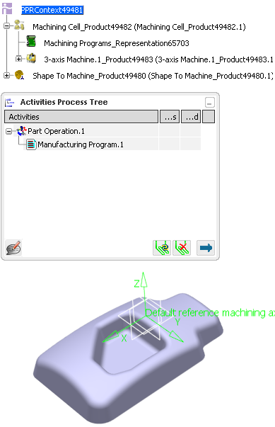
From any product:
- Alternatively, open an existing Machining Process or PPR context .
 By default,
the
Activities Process Tree opens
automatically.
By default,
the
Activities Process Tree opens
automatically.
- Alternatively, open an existing Machining Process or PPR context .
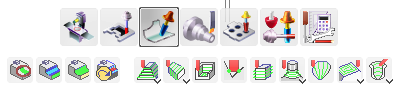
Click one of those icons to access the Machining Operation icons:
 Prismatic Machining Operations
 Surface Machining Operations
 Lathe Machining Operations
 Axial Machining Operations
The corresponding Machining Operation icons are displayed in a toolbar, e.g.
In the example below, we create a Sweeping operation. The operating mode is similar for all Machining Operations. See the Interface description in the Prismatic Machining User's Guide, 3-Axis Surface Machining User's Guide, Multi-Axis Surface Machining User's Guide, Multi-slide Lathe Machining User's Guide for more information on each Machining Operation.
Click the required Machining Operation icon and select a Manufacturing Program or another Machining Operation in the Activities Process Tree.
The Machining Operation dialog box appears.
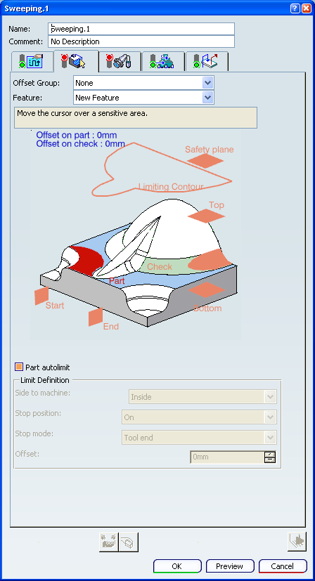
- It consists of several tabs:
 Geometry.
 Machining Strategy.
 Tools.
 Feeds and Speeds.
 Macros.
- Their status lights codes are as follows:
- green: all the requested data are defined,
- orange: data are defined, but modifications may be necessary,
- red: data definition is required.
Note:
- The status color codes are as follows:
- green (or the current value of Valuated parameters): all the requested data are defined,
- orange ((or the current value of Optional parameters): data are defined, but modifications may be necessary,
- red (or the current value of Required parameters): data definition is required.
- The colors of Valuated parameters, Optional parameters, Required parameters are defined in Color and Highlight.
- You can display some Machining Operation dialog boxes with a simplified user interface. See User Interface.
- It consists of several tabs:
Click Tool Path Replay
 to compute and validate the tool path of the Machining Operation.
Click OK to validate and exit the dialog box.
The Machining Operation is created in the Activities Process Tree, under a Manufacturing Program.
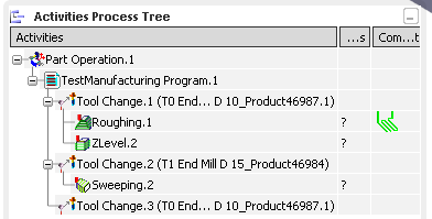
See Creating a Manufacturing Program and Machining Activities for more information about the position of the Machining Operation.