View | |||||||||
|
| ||||||||
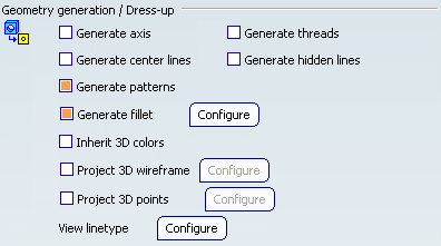
Geometry Generation / Dress-up
This category of options lets you specify what kind of geometry and dress-up elements you want to generate when generating views.

- Generate axis
-
Select this check box to generate axis lines.
Important: The view plane must be parallel to the rotation face axis. Rotation faces made out of fillets are not taken into account when generating axis lines. 
 By default,
this option is not selected.
 - Generate threads
-
Select this check box to generate threads.
Threads can be represented in two different ways:
- from the front and rear (whether or not the hole
is threaded along its whole depth).
Important: In this case, the view plane must be perpendicular to the rotation face axis. The face should be a threaded hole or a thread. The representation of the rotation face in the view must exceed 180 degrees. 
- from the side.
Important: In this case, the view plane must be parallel to the rotation face axis. The face should be a threaded hole or a thread. 

 By default,
this option is not selected.
 - from the front and rear (whether or not the hole
is threaded along its whole depth).
- Generate center lines
-
Select this check box to generate center lines.
Important: The view plane must be perpendicular to the rotation face axis. The representation of the rotation face in the view must exceed 180 degrees. 
 By default,
this option is not selected.
 - Generate hidden lines
-
Select this check box to generate hidden lines.
 By default,
this option is not selected.
 - Generate patterns
-
Select this check box to generate patterns.
 By default,
this option is selected.
 - Generate fillet
-
Select this check box to generate fillets.
Click Configure to configure fillet generation. Refer to Fillet Generation Dialog Box for more information.
 By default,
this option is selected.
 - Inherit 3D colors
-
Select this check box if you want the colors of a 3D shape to be automatically generated onto the views.
Important: Whenever the projected geometry color is the same as the sheet background color, the geometry color is changed to a more visible one, even if this option is selected. Thus, in the event the sheet and projected geometry are the same color, the inherited color may not be applied.  By default,
this option is not selected.
 - Project 3D wireframe
-
Select this check box to visualize both the wireframe and the geometry on generated views.
Click Configure to configure 3D wireframe projection. Refer to 3D Wireframe Projection Dialog Box for more information.
 By default,
this option is not selected.
 - Project 3D points
-
Select this check box to project points from 3D (no construction element).
Click Configure to configure 3D point projection. Refer to 3D Point Projection Dialog Box for more information.
 By default,
this option is not selected.
 - View Linetype
-
Click Configure to configure linetypes and thicknesses for specific types of views: section view, detail view, broken view, breakout view, skin section view (in the case of wireframes and surfaces). Refer to Linetype and Thickness Dialog Box for more information.
![]()
View Generation

- View generation mode
-
Select how you want to generate views. The options in the View generation mode combo box are as follows:
- Exact view: Select this option to generate exact views from the Design mode, i.e. views for which the geometry is available. The exact generation mode will be the best option in most cases.
- CGR : Select this option to generate views using the CGR format (CATIA Graphical Representation). CGR corresponds to a data format containing a graphical representation of the geometry only, which is available with the Visualization mode (as opposed to the exact geometry, which is available with the Design mode). With CGR, only the external appearance of the component is used and displayed; the geometry is not available. The corresponding .cgr file, if it exists, is inserted from the cache system.
- Approximate: Select this option to generate views in Approximate mode. Although Approximate
views are not as high in precision and quality as exact
views, this generation mode dramatically reduces memory
consumption. Performances may also be improved, depending
on how you fine-tune precision. Therefore, the Approximate
mode is particularly well-adapted to sophisticated products
or assemblies involving large amounts of data.
If you selected Approximate, click Configure to fine-tune the generation options according to your needs. Refer to Approximate Mode Dialog Box for more information.
- Raster: Select this option to generate views as images. This enables
you to quickly generate overall views for large products
or assemblies, regardless of drawing quality. Such views
are associative to the 3D geometry and can be updated when
the 3D shape or product changes.
If you selected Raster, click Configure to fine-tune the generation options according to your needs. Refer to Raster Mode Options Dialog Box for more information.
Important: To optimize disk space and memory consumption, it is recommended that you do not select the Inherit 3D colors option when generating raster views.
 By default,
Exact view is selected.
By default,
Exact view is selected.For a detailed description (including the advantages and restrictions pertaining to each view generation mode), refer to View Creation > About the View Generation Modes in the Generative Drafting User's Guide.
- 3D extracted representations
-
Select the type of 3D representation that you want to project in the view. The options in the 3D extracted representations combo box are as follows:
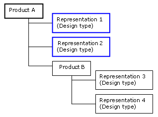
- All design representations: Select this option to create a view from all design representations.
- First design representations: Select this option to create a view from only the first level of design representations.
In the example below, the first design representations are surrounded in blue.

- As session : Select this option to create a view from all 3D representations in session.
 By default,
All design representations is selected.
 - Only generate 3D shapes larger than
-
Select this check box to specify that you only want to generate 3D shapes which are larger than a certain size, and indicate the appropriate size by providing a value in millimeters in the appropriate field.
 By default,
this option is not selected.
 - Enable occlusion culling
-
Select this check box if you want to save memory when generating exact views from an assembly which is loaded in Visualization mode (i.e. when the Work with the cache system option is active). This will load only the 3D shapes which will be seen in the resulting view (instead of loading all of them, which is the case by default), which optimizes memory consumption and CPU usage.
To ensure the efficiency of this option, make sure that the Exact preview for view generation option is not selected.
In the case of an assembly which is loaded in Design mode, or in the case of a 3D shape, the Enable occlusion culling option will help increase performance by reducing CPU usage.
Note: Keep the following restrictions in mind when selecting the Enable occlusion culling option:
- The Project 3D points option will be disabled.
- The only option available for Project 3D wireframe is Can be hidden.
Important: If you choose to project 3D wireframe, you will need to make sure that your wireframe elements have been taken into account when the CGR data was created: this is the case if you activated the Save lineic elements in cgr option from Tools > Options > Infrastructure > Product Structure > Cgr Management before the creation of CGR data (i.e. before you launched the 3D shape or product in Visualization mode). If not, you need to activate the Save lineic elements in cgr option and then re-create the CGR data. To do this, close all open 3D shapes and products and exit the application. Then, delete your CGR data from the cache. (The cache location is specified in Tools > Options > Infrastructure > Product Structure > Cache Management tab, Path to the local cache field.) Finally, re-open the product in Visualization mode.  By default,
this option is not selected.
![]()
Clipping view
![]()
- Put in no show dimension on non-visible geometry
-
Select this check box if you want the dimensions to put automatically in no show mode which are attached to geometry that is not visible in clipping views.
If you do not select this check box, dimensions are displayed in clipping views using the colors defined in the Element's Analysis Dialog Box, accessible via Tools > Options > Mechanical > Drafting > Display tab, Activate Elements' analysis.
The color used depends on whether the dimension is interactive (that is, created manually) or generated automatically:
- interactive dimensions are displayed using the color defined for dimensions on non-visible geometry (light blue by default).
- generated dimensions are displayed using the color defined for dimensions generated from 3D constraints (light green by default).
Important: Dimensions are put in no show mode only if none of the geometrical elements to which the dimension is attached are visible. If an element is visible while the other is not, the dimension is displayed using the color defined by the analysis display mode as specified above.  By default,
this option is selected.
![]()
View From 3D

- Generate 2D geometry
-
Select this check box if you want to generate 2D geometry (i.e. wireframe and 2D points) when generating a view from 3D from a layout view (2D Layout for 3D Design workbench).
 By default,
this option is selected.
 - Synchronize during update
-
Select this check box if you want to synchronize the view generated from 3D, during the update process, when the following specifications have been changed in 3D:
- the supporting plane (Functional Tolerancing and Annotation workbench and 2D Layout from 3D Design workbench)
- the back-clipping plane (2D Layout from 3D Design only)
 By default,
this option is selected.