Creating a Circular Milling Operation | ||||
|
| |||
Activate the Manufacturing Program and click Circular Milling
 in the Axial Machining Operations toolbar.
A Circular Milling entity is added to the Manufacturing Program.
The Circular Milling dialog box appears directly at the Geometry tab
 . This tab includes a sensitive icon to
help you specify the
geometry.
Areas of the icon are colored red indicating that this
geometry is required.
 Still in the Geometry tab:
- Enter Offset values for the Bottom and Contour, if required.
- Select the red hole depth representation then select hole
geometry in the authoring window. Double-click to end your selections.
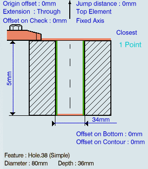
- Select the axis representation in the sensitive icon to invert the tool axis direction, if required.
- Choose the Machining mode: Standard or Helical.
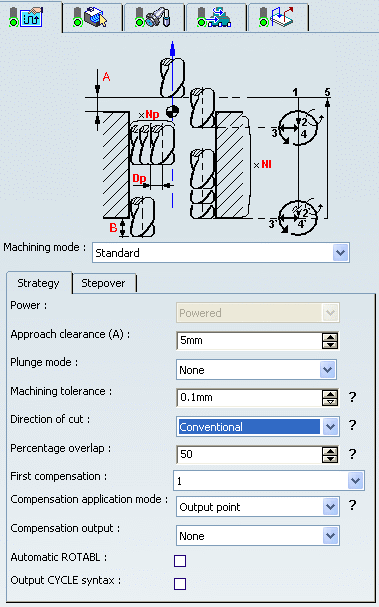
- Specify the machining strategy parameters.
The following are common to both machining modes:
- Approach clearance (A)
- Plunge mode
- Machining tolerance
- Direction of cut
- Percentage overlap
- Compensation number depending on those available on the tool
- Compensation application mode: Output point or Guiding point
- Compensation output, which allows you to manage the generation of Cutter compensation (CUTCOM) instructions in the NC data output.
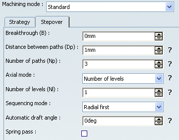
The Stepover parameters when Machining mode is Standard:
- Breakthrough (B)
- Distance between paths (Dp) and Number of paths (Np)
- Axial mode: Maximum depth of cut or Number of levels (with or without top)
- Sequencing mode: Axial first or Radial first
- Automatic draft angle.
- Spring pass
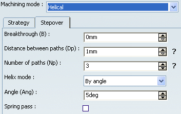
The Stepover parameters when Machining mode is Helical:
- Breakthrough (B)
- Distance between paths (Dp) and Number of paths (Np)
- Helix mode: By angle or By pitch
- Angle (Ang) or Pitch (P) value.
- Spring pass
Go to the Tool tab
 to select a tool.
See Specifying a Tool Element in a Machining Operation
You can use any of the following tool types:
- End Mill
- Face Mill
- Conical Mill
- Drill
- Spot Drill
- Countersink
- T-slotter
Select the Feeds and Speeds tab
 to specify the feedrates
and spindle speeds for the operation.
to specify the feedrates
and spindle speeds for the operation.Note: In the tool path represented in the Strategy tab, tool motion is at:
- Motion at machining feedrate from 1 to 2
- Motion at feedrates defined on macros from 2 to 3, 3 to 4, 4 to 2', 2' to 3' and 3' to 4'
- Retract at retract feedrate from 4' to 5.
Select the Macro tab
 to add approach and retract motions to the operation.
See Defining Macros on Axial Machining Operations
- Select Predefined Helix to insert a helix approach macro
The Predefined-Helix mode is available for approach macro and the return between level approach macro in Standard machining mode.
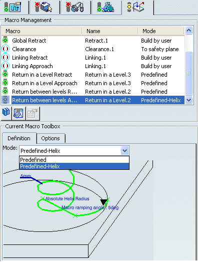
The sketch below the mode changes to Helix motion. - Double-click Helix Radius (5mm) on the manipulator.
The Edit Parameter dialog box appears and allows you to change the radius value.

- Double-click Macro Ramping Angle on the manipulator.
The Edit Parameter dialog box comes and allows you to change the macro ramping angle value.

- Double-click Absolute Helix Radius on the manipulator, or click Parameter in the contextual
menu.
The following dialog box appears and allows you to change the value.
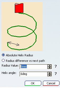
- Click the manipulator to change the radius state can be changed from Absolute Helix Radius to Radius difference vs next path.
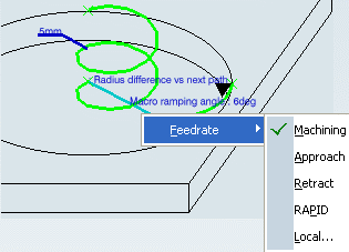
- Right-click an arc of helix manipulator and select the Feedrate type from the contextual menu.
- Select Predefined Helix to insert a helix approach macro
Click Tool Path Replay
 to check the validity of the operation.
- The tool path is computed.
- A progress indicator is displayed.
- You can cancel the tool path computation at any moment before 100% completion.
Click OK to create the operation.
Note: If your PP table is customized with the following statement for Circular Milling operations:
CYCLE/CIRCULARMILLING, %MFG_TOTAL_DEPTH,
%MFG_FEED_MACH_VALUE,&MFG_FEED_UNIT, %MFG_CLEAR_TIP
A typical NC data output is as follows:
CYCLE/CIRCULARMILLING, 38.500000, 500.000000, MMPM, 2.500000
The parameters available for PP word syntaxes for this type of operation are described in the NC_CIRCULAR_MILLING section of the Manufacturing Infrastructure User's Guide.
Click Edit Cycle
 to edit or choose output syntaxes.