Defining Macros on Axial Machining Operations | ||||||
|
| |||||
From any product:
- Alternatively, open an existing Machining Process or PPR context .
 By default,
the
Activities Process Tree opens
automatically.
By default,
the
Activities Process Tree opens
automatically.
- Alternatively, open an existing Machining Process or PPR context .
Activate the Manufacturing Program.
- Click
 Axial Machining Operations.
 - Click
 Drilling in the sub-toolbars that appear.
 - Go to the Macros tab
 in the Machining Operation dialog box that appears.
The initial status of all the macros in the Macro Management list is Inactive
 .
.- Click
Right-click the Approach macro line and select Activate in the contextual menu.
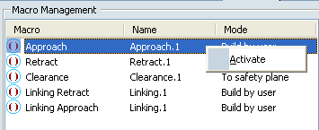
The macro line is activated.
turns to  , meaning some definition data exist but may require modifications.
In the Current Macro Toolbox, select Add Axial Motion
 .
.
A sensitive icon representing the elementary paths of the macro appears.
Double-click 10mm to edit the distance (to 30mm, for example).
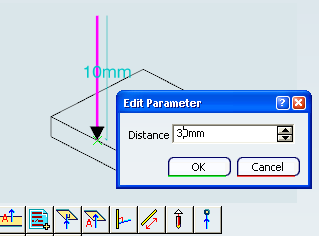
The yellow light turns to green, meaning the data are up-to-date.
Click Tool Path Replay
 to check the axial approach.
 Under Macro Management, as you did above:
- Click Tool Path Replay
to check the defined motions.
Note: If a jump distance is defined in the Machining Operation, it is used in preference to the linking macro. Similarly if local entry/exit distances are defined on the Machining Operation, they are used in preference to the linking macro.
- Click Tool Path Replay
Click Tool Path Replay
to validate the tool path.- In the Replay dialog box,
select the Different colors mode
 in order to visualize feedrate changes. See Color Modes.
The tool path is displayed with the following default colors:
- Yellow: approach feedrate
- Green: machining feedrate
- Blue: retract feedrate
- Red: Rapid feedrate
- Purple: plunge feedrate
- White: local feedrate.
- In the Replay dialog box,
select the Different colors mode