Creating a Chamfering Two Sides Operation | ||||
|
| |||
Activate the Manufacturing Program and click Chamfering Two Sides
 in the Axial Machining Operations toolbar.
A Chamfering Two Sides entity is added to the Manufacturing Program.
The Chamfering Two Sides dialog box appears directly at theGeometry tab
 . This tab includes a sensitive icon to
help you specify the
geometry.
Areas of the icon are colored red indicating that this
geometry is required.
. This tab includes a sensitive icon to
help you specify the
geometry.
Areas of the icon are colored red indicating that this
geometry is required. Still in the Geometry tab:
- Select the red hole depth representation then select the
hole geometry in the authoring window. Double-click to end your selections.
- Select the red hole depth representation then select the
hole geometry in the authoring window. Double-click to end your selections.
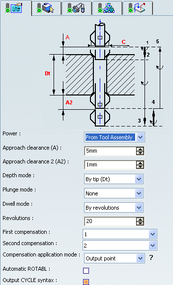
Select the Strategy tab
 and specify the following
machining parameters:
and specify the following
machining parameters:- Approach clearance (A) and Approach clearance 2 (A2)
- Depth mode: By tip (Dt)
- Dwell in seconds
- First compensation number depending on those available on the tool for top chamfering
- Second compensation number depending on those available on the tool for bottom chamfering.
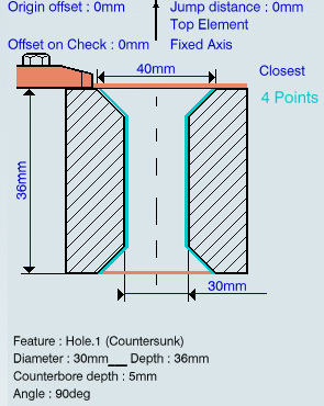
Note: The depth value and chamfer diameter are retrieved from your geometry selections.
Go to the Tool tab
 to select a tool.
Select the Feeds and Speeds tab
 to specify the feedrates
and spindle speeds for the operation.
to specify the feedrates
and spindle speeds for the operation.Note: In the tool path represented in the Strategy tab, tool motion is as follows:
- Motion at machining feedrate from 1 to 2
- Dwell for specified duration
- Possibly, activation of second tool compensation number (output point change)
- Motion at approach feedrate from 2 to 3
- Motion at machining feedrate from 3 to 4
- Dwell for specified duration
- Possibly, activation of first tool compensation number (output point change)
- Retract at retract feedrate from 4 to 5.
Select the Macro tab
 to add approach and retract motions to the operation.
Click Tool Path Replay
 to check the validity of the operation.
Note: For material removal simulations, Two Sides Chamfering tools are not supported for Photo mode and are not collision checked in Video mode.
- The tool path is computed.
- A progress indicator is displayed.
- You can cancel the tool path computation at any moment before 100% completion.
Click Edit Cycle
 to edit or choose output syntaxes.