Sequential Axial and Sequential Groove Operations | |||||
|
| ||||
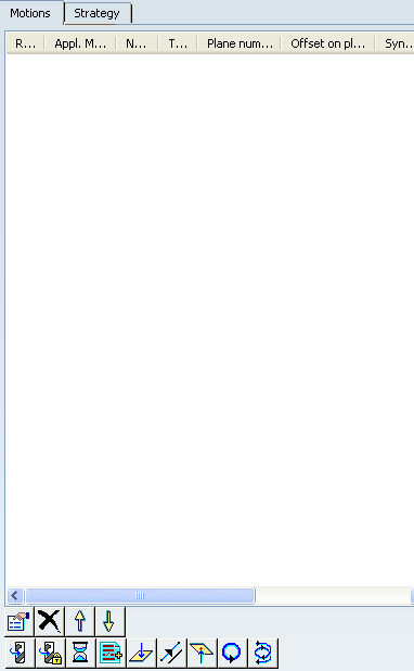
Motions Parameters
 Properties
- Edits the motion selected in the dialog box.
 Delete
- Deletes the motion selected in the dialog box.
 and
and 
- Changes the rank of the motion selected in the dialog box.
 Spindle Speed
- Inserts a tool
motion defined by a spindle speed.
- Spindle mode
- Specifies spindle mode as Machining / Local spindle speed.
- Local Spindle
- Specifies the value and unit of local spindle speed.
Note:
The spindle speed can be defined in linear (length per minute) or angular (length per revolution) units.
- : length in revolutions per minute and unit is set to mm_turn.
- Linear: length in feed per minute and unit is set to mm_mn.
- Way of rotation
- Specifies way of rotation as CLW/CCLW
NC_SPINDLE NC command is generated in output file. Example:
SPINDL/500,RPM
 Spindle Stop
- Inserts a tool
motion defined by a spindle stop or lock.
Spindle stop: NC_SPINDL_STOP NC command is generated in output file
Spindle lock: NC_SPINDL_LOCK NC command is generated in output file.
 Delay
Delay- Inserts a tool motion
defined by a delay (in spindle revolutions or time).
NC_DELAY NC command is generated in output file. Example:
DELAY/2,REV
 PP Word
- Inserts a tool motion defined by PP word statements (access to a PP word table is available if one is defined on the machine of Part Operation).
 Go to Plane
 - Inserts a tool
motion defined by an axial motion to a plane defined and numbered
1 to 5 in the Geometry tab. The motion is done normal
to the plane.
- Plane number
- Specifies plane number between 1 to 5.
- Offset on plane
- This offset is added to the offset that can be
set on the geometric element selected in the Geometry
tab.
Note:
- Offset is positive along the tool axis direction and negative on the opposite direction.
- Offset defined on the selected element (plane) and the offset defined on the motion are both taken into account to compute the tool position.
- Feedrate mode
- Allows definition of Machining, Approach, Retract, RAPID, or Local feedrate (including feedrate unit when local feedrate is defined).
- Compensation
- Allows definition of the compensation point for this motion.
The compensation is activated at the start of the motion.
NC_COMPENSATION syntax is generated in the output file when the compensation point is different from previous motion. Example:
LOADTL/2,5
 Go Delta
- Inserts a tool motion
defined by a displacement specified by DX, DY, DZ values. Positive
DZ value is defined along the machining hole axis.
See Feedrate Mode and Compensation.
 Go to Clearance
- Inserts a
tool motion defined by an axial motion up to clearance plane
(defined by the Approach clearance).
The tool tip can reach the plane defined by the approach clearance
displayed on the Strategy tab .
See Feedrate Mode and Compensation.
 By default,
If no Go to Clearance motion is defined in the motion list,
an automatic motion is done from the last position reached by
the tool motion (last sequential motion) up to the clearance
plane (defined by the Approach clearance). This automatic
motion is done at RAPID feedrate.
By default,
If no Go to Clearance motion is defined in the motion list,
an automatic motion is done from the last position reached by
the tool motion (last sequential motion) up to the clearance
plane (defined by the Approach clearance). This automatic
motion is done at RAPID feedrate.  Circular
- Inserts a tool motion
defined by approach, retract and complete circular motions,
which are defined in the icon of the dialog box.
Available in Sequential Groove only.
Tool path is generated as follows.
- Approach motions, full circular motion (on the selected diameter + offset), and retract motions.
- Approach and retract motions can be activated or deactivated (the complete circular motion cannot be deactivated).
- Feedrate type or local value (including feedrate unit) can be set on each motion.
- Circular approach and retract motion parameters can be set.
- Offset on diameter
- Offset taken into account for tool path computation (positive value defines offset inside the circle and negative value defines offset outside the circle).
- Direction of cut
- Specifies how machining is to be done.
Yopu can specify: Climb / Conventional (direction of motion is done to respect cutting condition).
- Spring pass
- Select this check box to define an optional circular motion before retract
motion.
By default,
the check box is not selected.
 Helical
- Inserts a tool motion
defined by approach, retract, and complete helical motions, which
are defined in the icon of the dialog box. Available in Sequential Groove only.
Tool path is generated as follows.
- Approach and retract motions can be activated or deactivated (the helical motion cannot be deactivated).
- Feedrate type or local value (including feedrate unit) can be set on each motion.
- Circular approach and retract motions parameters can be set.
- Offset on diameter
- Offset taken into account for tool path computation (positive value defines offset inside the contour and negative value defines offset outside the contour).
- Plane
- Defines the plane to reach (can be plane 1 or plane 2 of the level).
- Offset on plane
- This offset is added to the offset that can be set on the geometric element selected in Geometry tab.
- Helix mode
- Specifies helix mode as By angle/By pitch. Angle or pitch value is displayed in Angle(Ang) or Pitch (P).
- Direction of cut
- Specifies the direction of cut for tool as Climb / Conventional
Note:
- The up/down helical motion direction is defined with the plane to reach. Up or down helical motion is defined with the difference between the current position and the plane to reach.
- Helical interpolation instructions can be generated in the output file (APT source and Clfile) for helical tool motions.
- Approach and retract motions are not done with a helical tool path.
![]()
Strategy Parameters
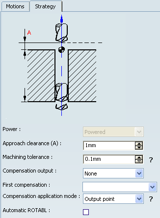
- Power
- See Power
- Approach clearance
- Defines a safety distance along the tool axis for approaching the hole reference.
- Machining tolerance
- Specifies the maximum allowed distance between the theoretical and computed tool path.
- Compensation output
- Defines automatic activation/deactivation of CUTCOM statements
for all circular and helical trajectories
You can specify:
- None
- 2D Radial profile
- 2D Radial tip
- First compensation
- Specifies the tool corrector identifier to be used in the operation. The corrector type (P1, P2, P3, for example), corrector identifier, and corrector number are defined on the tool. When the NC data source is generated, the corrector number can be generated using specific parameters.
- Compensation application mode
- Specifies how the corrector type specified on the tool (P1,
P2, P3, for example) is used to define the position of the tool:
You can specify:
- Automatic ROTABL
- Select this check box to allow the generation of rotation motions between drilling points that have different tool axes. This capability works with a 3-axis milling machine with rotary table when ROTABL/ output is requested.
![]()
Geometry
Sequential Axial and Sequential Groove operations inherit options and behavior available on axial operations: Check element selection, Offset on check, Top element selection, Top element/Projection, Origin offset, Jump distance, machining points to select (selection and management of machining points), ordering capability (Closest, Manual, By Band, Reverse Ordering), machining pattern selection, and so on. Refer to 2.5 to 5-Axis Drilling Operations for more information.
For both operations, the geometry ( ) (hole to machine)
is managed in the Global tab. The additional geometry
(planes or depth and offsets) is managed in the Local
tab. However, there are some differences concerning geometry
selection.
) (hole to machine)
is managed in the Global tab. The additional geometry
(planes or depth and offsets) is managed in the Local
tab. However, there are some differences concerning geometry
selection.
- Sequential Axial operation
- Geometry selection is dedicated to hole machining. You define planes (and offset) or depth value to manage axial tool path between planes.
- Any number of planes can be selected and used for the tool motions.
- Sequential Groove operation
- Geometry selection is dedicated to groove machining. You define planes, diameters (and offsets), or values to manage axial and circular motions.
- Up to 10 machining levels can be defined: two planes and one diameter can be defined on each level.
- The sequential motions defined in the list are applied to each groove level: the list of motions is defined for a single level. At tool path generation, the motions are applied to each groove level.
![]()
Selection of Geometry
Geometry can be defined by selection of geometrical elements or by valuation of depth or diameter values.
When selecting a geometrical element to define the plane or diameter, the depth or diameter value is automatically displayed in the dialog box.
The depth or diameter value can be modified. In this case the link with the corresponding geometry (plane, diameter) is lost: the corresponding plane (and offset) is reset.
In case of modified geometry (not up to date), a yellow status light is displayed in the Status column of Activities Process Tree.
In case of lost geometry (geometry not found), a red status light is displayed in the Status column of Activities Process Tree.
For a sequential motion on which geometry is not found, the character (?) is displayed in the Status column of Activities Process Tree.
![]()
Global and Local Geometry for Sequential Axial Operations
Global tab: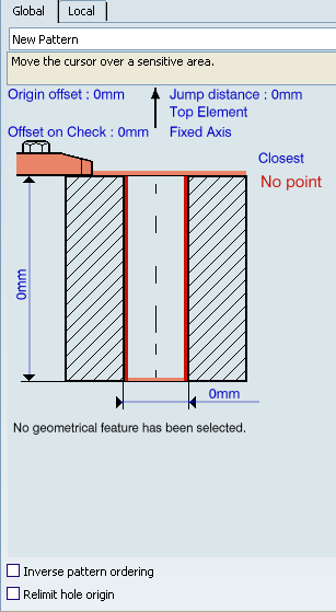
- Hole diameter and depth
- Initialized from point selection, these values are not used for tool path computation but are displayed for information. They can be can be used by f(x) formula.
- Inverse pattern ordering
- Select this check box to reverses the order of machining holes.
- Relimit hole origin
- Select this check box to determine the
hole origin according to tool axis (when design hole is selected).
For more details, See Geometry.
Local tab: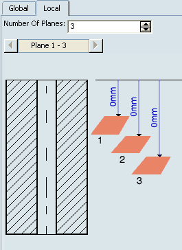
- Number of planes
- Any number of machining
planes can be defined. They are presented in groups of five maximum in the sensitive
icon of the Local tab.
The distance to each machining plane is defined by entering a value or by selecting a geometrical element (plane, planar surfaces, planar edge, or point). These values are defined for the first machining hole and the same values are used to machine all the machining holes.
![]()
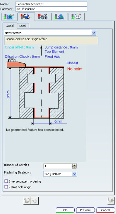
Global and Local Geometry for Sequential Groove Operations
Global tab: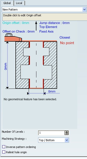
- Hole diameter and depth
- Initialized from point selection, these values are not used for tool path computation but are displayed for information. They can be can be used by f(x) formula.
- Number of levels
- A maximum of 10 levels can be specified.
- Machining strategy
- Defines how the different levels are taken into account:
- For Top/Bottom strategy, the first level to machine depends on the Plane 1 axial position. The level to machine is determined according to the distance from hole origin to the Plane 1 of a level. The first level to machine is the level on which Plane 1 is the upper one.
- For Bottom/Top strategy, the first level to machine depends on the Plane 2 axial position. The level to machine is determined according to the distance from hole origin to the Plane 1 of a level. The first level to machine is the level on which Plane 2 is the lower one.
- Inverse pattern ordering
- Reverses the order of machining holes.
- Relimit hole origin
- Determines the hole origin according to tool axis (when design hole is selected).
Local tab: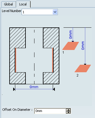
- Level number
- The geometry linked to the selected level number is displayed.
- Machining diameter
- Defines a diameter value or select an element (circular edge).
- Offset on diameter
- Defines the offset to be used on the defined diameter (or selected circular element). A positive value defines an offset inside the diameter. A negative value defines an offset outside the diameter.
![]()
Tools
All
- milling tools
 and
and - drilling tools

(except Barrel Mills  ) can be used in this type of operation.
![]()
Feedrates and Speeds Parameters
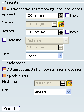
- Feedrate: Automatic compute from tooling Feeds and Speeds
- This check box allow an operation's feeds and speeds values to be updated automatically when the tool's feeds and speeds values are modified.
You can specify the following feedrates:
- Approach
- Machining
- Retract
- Rapid: In Point to Point operations, a local feedrate can be defined for all tool motions (except the first motion, which must be either RAPID or a specific feedrate). The local feedrate is applied instead of the machining feedrate during the tool motion to reach the tool position. For the operation start point, machining feedrate is taken into account.
Note:
The above feedrates can be defined in linear (feed per minute) or angular (feed per revolution) units.
- Angular: feedrate in revolutions per minute and unit is set to mm_turn.
- Linear: feedrate in feed per minute and unit is set to mm_mn.
- Transition
- You can locally set the feedrate for a transition path to a
machining operation B from a machining operation A or from a tool
change activity. This is done by selecting the Transition check box in the Machining Operation dialog box for
operation B.
For more information, please refer to the Setting a Transition Feedrate.
- Spindle Speed: Automatic compute from tooling Feeds and Speeds
This check box allow an operation's feeds and speeds values to be updated automatically when the tool's feeds and speeds values are modified.
If the Feedrate Automatic compute check box is selected and the Spindle Speed: Automatic compute from tooling Feeds and Speeds check box is not selected, then only the feedrate values can be computed. If both are not selected then automatic updating is not done.
When you modify a tool's feeds and speeds, all existing operations with the Automatic compute check boxes selected that use this tool (or an assembly using this tool) can be recomputed.
- Spindle output
- This check box manage output
of the SPINDL instruction in the generated NC data file:
- If the check box is selected, the instruction is generated.
- Otherwise, it is not generated.
Note:
Spindle speed is applied on the different motions of the operations (including approach, retract, linking macros). Spindle can be re-defined with Spindle tool motion.
The spindle speed can be defined in linear (length per minute) or angular (length per revolution) units.
- Angular: length in revolutions per minute and unit is set to mm_turn.
- Linear: length in feed per minute and unit is set to mm_mn.
- Compute
- Feeds and speeds of the operation can be updated according to tooling feeds and speeds by clicking the Compute button located in the Feeds and Speeds tab of the operation
Feeds and speeds of the operation can be updated automatically according to tooling data and the Rough or Finish quality of the operation. This is described in About Feeds and Speeds.
![]()
NC Macros
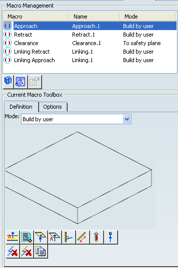
You can define transitions paths for:
- Approach: to approach the operation start point.
- Retract: to retract from the operation end point.
- Linking: Linking between machining holes of the same pattern
- Clearance: Used to define the feedrate on the horizontal path between two machining positions.
The proposed macro mode are:
- None
- Build by user
For more information, please refer to the Defining Macros.