Creating a Sequential Groove Operation | ||||
|
| |||
Open a typical part with two grooves to machine like the one shown below:
Activate the Manufacturing Program and click Sequential Groove
 in the Axial Machining Operations toolbar.
A Sequential Groove entity is added to the Manufacturing Program.
The Sequential Groove dialog box appears directly at the Geometry tab
 . This tab includes a sensitive icon to
help you specify the
geometry.
Areas of the icon are colored red indicating that this
geometry is required
. This tab includes a sensitive icon to
help you specify the
geometry.
Areas of the icon are colored red indicating that this
geometry is requiredStill in the Geometry tab.
- Double click to end your selections.
- For Level Number 1, select the plane representations
in the sensitive icon, and the planes of the first groove
in the part.
The Local tab is updated as shown below.
- Double click to end your selections.
Select the Strategy tab
 ,
which comprises two tabs Motions (to define the
elementary motions making up the machining operation) and Strategy.
,
which comprises two tabs Motions (to define the
elementary motions making up the machining operation) and Strategy.
- Click Go to Plane
 ,
then define a Go to Plane motion to Plane 1 and a Local
Feedrate of 50mm/mn. Set Compensation to 2.
,
then define a Go to Plane motion to Plane 1 and a Local
Feedrate of 50mm/mn. Set Compensation to 2.

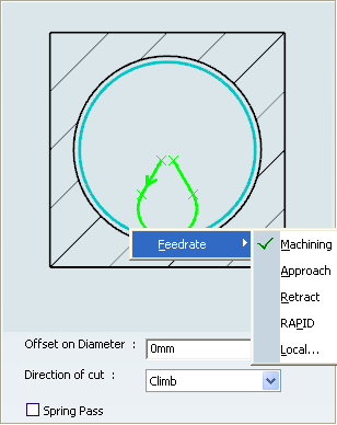
- Click Circular
 ,
then define a circular motion
,
then define a circular motion
- Click Go to Plane
,
then define a Go to Plane motion to Plane 2 and a Local
Feedrate of 50mm/mn. Set Compensation to 1.
- Insert other motions as follows:
- Circular motion with Feedrate=Machining
 Go to Clearance motion with
Local Feedrate of 500mm/mn.
Right-click this motion in the list
and set the Application mode
to Last level.
Go to Clearance motion with
Local Feedrate of 500mm/mn.
Right-click this motion in the list
and set the Application mode
to Last level.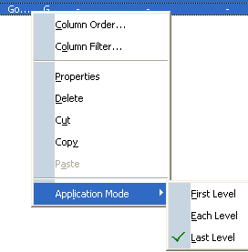
- Go to the Strategy tab
.
- Click Go to Plane
Go to the Tool tab
 to select a tool.
See Specifying a Tool Element in a Machining Operation
- Click More >> and go to the Compensation tab to specify a second corrector
P2 as follows:
- Click More >> and go to the Compensation tab to specify a second corrector
P2 as follows:
Select the Feeds and Speeds tab
 to
specify the feedrates and spindle speeds for the operation.
to
specify the feedrates and spindle speeds for the operation. Select the Macros tab
 to specify the desired transition paths.
Click Tool Path Replay
 to check the validity of the operation.
- The tool path is computed.
- A progress indicator is displayed.
- You can cancel the tool path computation at any moment before 100% completion.