Plunge Milling | |||||
|
| ||||
![]()
Machining Parameters
- Machining tolerance
- Specifies the maximum allowed distance between the theoretical and computed tool path. Consider the value to be the acceptable chord error.
- Minimum plunging length
- Specifies the minimum plunging length. If the distance to be machined along Z on one of the points is lower than the minimum plunging length, this point is not machined.
![]()
Axial Parameters
- Axial safety distance
- Specifies axial safety distance.
- Distance after first cut
- Specifies distance after first cut.
- Distance before bottom
- Specifies distance before bottom.
- Lateral retract distance
- Specifies lateral retract distance.
- Raise distance
- Specifies raise distance.
- Axial corner radius
- Specifies axial corner radius.
Note:
A larger raise distance or a
larger axial corner radius removes more material on
the bottom:
The retract motion is defined by Lateral retract distance and Raise distance. Its direction is automatically defined by the position of the tool in the material. The motion is done insuring that the tool cannot be damaged (no machining during this motion): there is a check with the remaining material of the stock.
![]()
Grid Parameters
- Grid Type
- Specifies grid type.
You can specify:
- Points: When Points is selected as Grid Type, the Grid tab is not available.
Click Points and select points in the authoring window. The selection order defines the machining order. Right-click Points to access the following contextual menu.
Right-click small points to access the following contextual menu.
- Automatic Ordering
- Select Automatic Ordering to re-order all the
points as shown in the dialog box.
- Order
- Specifies order By Band / Closet.
- Style
- Specifies style as Concentric. This is avaiable when order is By Band.
- Width
- Specifies width. This is avaiable when order is By Band.
- Mode
- Specifies mode as Clockwise/Conterclockwise, or Either. This is avaiable when order is By Band.
- Renumber
- Select Renumber to change the order of individual points. .
- No material check
- Select No material check to disable the material check on individual points.
- Contours: Click Contours and select contours in the authoring window.
The contours may be ordered or not, closed or not. The contact points are computed from those contours, using the Maximum cutting progress. The initial ordering of the points on a contour follows the orientation of the contour. To ensure a correct ordering of the points, you can renumber the contours using the contextual menu.
- Rectangular:Click Grid center and select points in the authoring window.
The grid is defined by two step values, a direction, and a center point. The order of the plunges is fixed.
Note:
- The initial drilling and first groove is not necessary for center cutting plungers.
- The initial drilling is not necessary for external areas.
- Defining a Grid center is optional, unless you want to control the first drilling point (e.g. full material machining). If you choose to define one, it can be a point external to the grid.
the computation of the grid is based on the default Longitudinal direction.
Starting from the grid center, the grid is computed along a longitudinal direction. First, the tool machines a groove and then reaches each of the points of the grid with a constant fixed order defined by machining style.
- Longitudinal direction
- Available in the sensitive icon, lets you edit the required direction in the dialog
box that is displayed.
- Maximum cutting progress
- The contact points are computed using the Maximum cutting progress.
- Longitudinal step
- Specifies the longitudinal step.
- Machining style
- Specifies machining
style.
You can specify
- Zig-zag
- One-way, the Machining side appears when One-way is specified as Machining style.
- Machining side
- Specifies machining side.
You can specify
- Left: material is on the left of the tool.
- Right: material is on the right of the tool.
- Grrove width and Groove step
- The groove has a specific Groove step and a
specific Groove width.
 By default,
Groove width is the
tool diameter.
By default,
Groove width is the
tool diameter.You can define a larger Groove width but it cannot exceed twice the tool diameter. In that case, the groove can be machined in Zig-zag machining style. The machining style of the groove is independent from the strategy used to machine the rest of grid.
- By Offset: Click Contours and select points in the authoring window.
The contour must be continuous. You can apply an Offset on contours. You can modify their direction by clicking the arrow.The grid is computed as follows:
with First Offset = Offset of contour + Offset on walls + Diameter of tool / 2.- Maximum cutting progress
- Specifies discretization step on the contours.
- Finished cutting progress
- Specifies step on the initial groove.
- Plunge on the contour
- Select this check box to let the tool plunge on the contour. In this case, the first offset is the value of the Grid parameter Offset.
- Contour number
- Specifies Contour number at least 1.
- Offset
- Specifies offset value.
- Machining Direction
- Specifies machining direction as Inward or Outward.
- Machining style
- Specifies Machining style as One-way or Zig-zag. The Machining side appears when One-way is specified as Machining style
- Machining side
- Specifies machining side.
You can specify
- Left: material is on the left of the tool.
- Right: material is on the right of the tool.
- No Show Points
When the Grid type is Rectangular or By Offset, the toggle No Show Points/Show Points lets you visualize the plunging points before computing the tool path:
- you must have selected the geometry,
- the machining parameters must be valid,
- the visualization of the plunging points is updated when you modify the strategy parameters,
- the toggle must be on No Show Points when you select or modify geometry.
The visualization consists of labels giving the rank of the points and arrows showing how they are linked.
When dealing with thousands of points, the visualization turns to crosses.Note:
- visualizing plunge points may be time consuming,
- the visualization is computed from the real geometry of the rough stock and the minimum plunging length, meaning the visualization may compute more points than needed by the tool path.
- Points: When Points is selected as Grid Type, the Grid tab is not available.
![]()
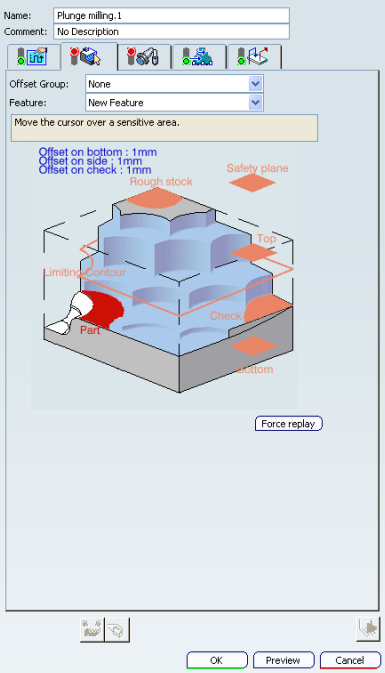
Geometry
From the sensitive icon, you can define the following geometry:
- Part with possible offset.
- Rough stock (optional).
- If you do not select a rough stock, the rough stock defined at the Part Operation level is taken into account to compute the material remaining after all the operations placed before the Plunge Milling operation.
- The rough stock can only contain a plane or a planar face: the rough stock taken into account are the material between this face and the part.
- Offset on bottom: this is the offset on horizontal areas.
- Offset on side: this is the offset on vertical areas.
- Check element with possible offset. The check element is often a clamp that holds the part and therefore is not an area to be machined.
- Safety plane, that is the plane that the tool can rise to at the end of the tool path
in order to avoid collisions with the part. You can also define a
new safety plane with the Offset option in the safety plane
contextual menu.
The new plane can be offset from the original by the distance that you enter in the dialog box along the normal to the safety plane. If the safety plane normal and the tool axis have opposed directions, the direction of the safety plane normal is inverted to ensure that the safety plane is not inside the part to machine.
- Top plane which defines the highest plane that can be machined on the part.
- Bottom plane which defines the lowest plane that can be machined on the part.
- Limiting contour which defines the machining limit on the part.
Note: The plunging points are computed and kept if they are inside the limit contour. The position of the tool can be on or inside the limiting contour.
![]()
Feedrates and Speeds Parameters
- Feedrate: Automatic compute from tooling Feeds and Speeds
- This check box allow an operation's feeds and speeds values to be updated automatically when the tool's feeds and speeds values are modified.
You can specify the following feedrates:
- Approach
- Machining
- Plunge
- Retract
- Finishing
Note:
The above feedrates can be defined in linear (feed per minute) or angular (feed per revolution) units.
- Angular: feedrate in revolutions per minute and unit is set to mm_turn.
- Linear: feedrate in feed per minute and unit is set to mm_mn.
- Transition
- You can locally set the feedrate for a transition path to a
machining operation B from a machining operation A or from a tool
change activity. This is done by selecting the Transition check box in the Machining Operation dialog box for
operation B.
For more information, please refer to the Setting a Transition Feedrate.
- Spindle Speed: Automatic compute from tooling Feeds and Speeds
This check box allow an operation's feeds and speeds values to be updated automatically when the tool's feeds and speeds values are modified.
If the Feedrate Automatic compute check box is selected and the Spindle Speed: Automatic compute from tooling Feeds and Speeds check box is not selected, then only the feedrate values can be computed. If both are not selected then automatic updating is not done.
When you modify a tool's feeds and speeds, all existing operations with the Automatic compute check boxes selected that use this tool (or an assembly using this tool) can be recomputed.
- Spindle output
- This check box manage output
of the SPINDL instruction in the generated NC data file:
- If the check box is selected, the instruction is generated.
- Otherwise, it is not generated.
Note:
Spindle speed is applied on the different motions of the operations (including approach, retract, linking macros). Spindle can be re-defined with Spindle tool motion. The spindle speed can be defined in linear (length per minute) or angular (length per revolution) units.
- Angular: length in revolutions per minute and unit is set to mm_turn.
- Linear: length in feed per minute and unit is set to mm_mn.
- Quality
- The feed and speed values are computed according to the Quality setting on the operation.
- Compute
- Feeds and speeds of the operation can be updated according to tooling feeds and speeds by clicking the Compute button located in the Feeds and Speeds tab of the operation.
Feeds and speeds of the operation can be updated automatically according to tooling data and the Rough or Finish quality of the operation. This is described in About Feeds and Speeds.
![]()
NC Macros
For more information, please refer to the Defining Macros.
The possible Approach and Retract macros are in Build by user mode.
The possible Clearance macros are:
- Optimized
- Along tool axis
The Clearance feedrate can be modified through its
contextual menu:![]()