Click Pad  in the Sketch-Based Features toolbar (Pads sub-toolbar).
The Pad Definition dialog box appears.
Click the Selection box.
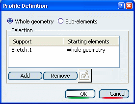
Right-click and select Go to Profile Definition .
The Profile Definition dialog box appears.

You can define whether you need the Whole geometry,
that is the whole sketch, or Sub-elements only.
For the purpose of our scenario, select Sub-elements
if not already done.
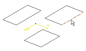
Select an edge.

The sketch name as well as the edge name appear in the dialog
box. The application also previews the pad.
Click Add to add another element.
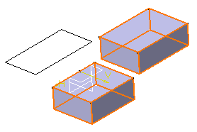
Select an edge belonging to another profile.
The application now previews this pad too.
Repeat steps 6 and 7 using an edge belonging to the
third profile.
Select edge2 from the starting elements box
and click Remove to remove the associated profile from the
selection.
Click OK to validate your selection.
The Pad Definition dialog box reopens. You
then just have to enter the parameters of your choice to extrude two
profiles.
Optional: : Click Preview
before confirming the creation.
