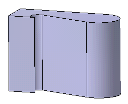
Select the profile to be extruded.
Click Pad
 in the Sketch-Based Features toolbar (Pads sub-toolbar).
The Pad Definition dialog box appears and the application
previews the pad to be created. By default, the application extrudes
normal to the plane used to create the profile. To know how to change the direction,
see Creating Pads not Normal to Sketch Planes.
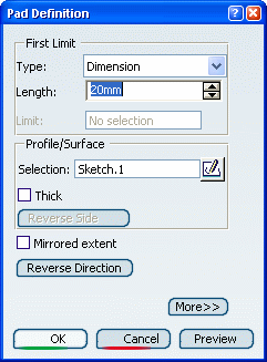
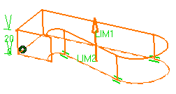
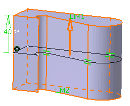
Keep Dimension as the limit type you want and enter 40 in the Length box to increase the length value.
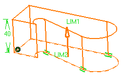
Click Mirrored extent to extrude the profile in the opposite direction using the same length value. If you wish to define another length for this direction, you do not have to click Mirrored extent . Just click More and define the second limit.
Optional:
Click Preview to see the result.
Click OK.
The pad is created. The specification tree indicates that it has been created.
