Creating a Part Operation | ||||||||
|
| |||||||
Create and Edit a Part Operation
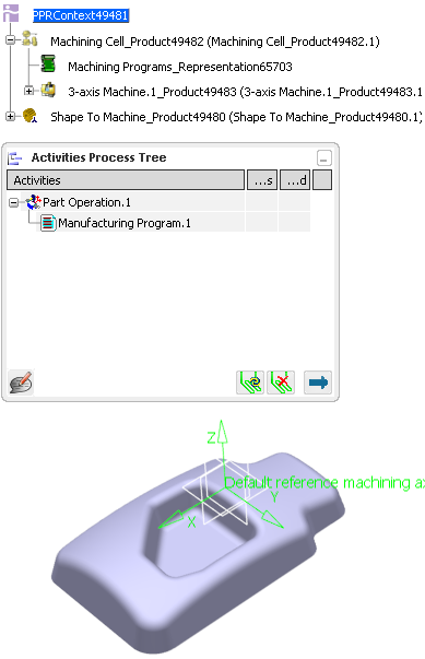
You can access and create a Part Operation in the Activities Process Tree.
- Alternatively, open an existing Machining Process or PPR context .
 By default,
the
Activities Process Tree opens
automatically.
By default,
the
Activities Process Tree opens
automatically.
- Alternatively, open an existing Machining Process or PPR context .
If you need to add a Part Operation, click NC Machine Control
 > Part Operation
  .
.
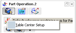
Double-click the Part Operation in the Activities Process Tree.
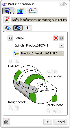
The dialog box to edit a Part Operation varies depending on the type of the machine.
- When the assigned machine is a milling machine, the Part Operation dialog box is:
- When the assigned machine is a millturn machine, the Part Operation dialog box is:
- When the assigned machine is a milling machine, the Part Operation dialog box is:
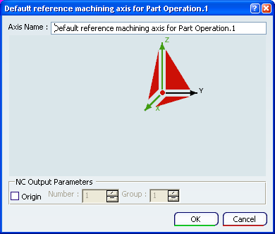
Optional: Click
 to edit the Part Operation Name and assign Comments to the
Part Operation.
to edit the Part Operation Name and assign Comments to the
Part Operation.Click Analyse
 to open the Geometry Analyser dialog box containing the selected geometry points.
Click Rest all selections
 to reset all geometry selections in the authoring window
Click Show/Hide the offset
 to show/hide the offsets in authoring window.
 .
.
![]()
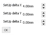
Define the Setup of the Part Operation
 .
. to
associate an existing setup assembly to the
to
associate an existing setup assembly to the  .
. 
![]()
Edit the Options of the Part Operation
You can edit several options of the Part Operation from the Option tab.
Only the relevant options are selectable.
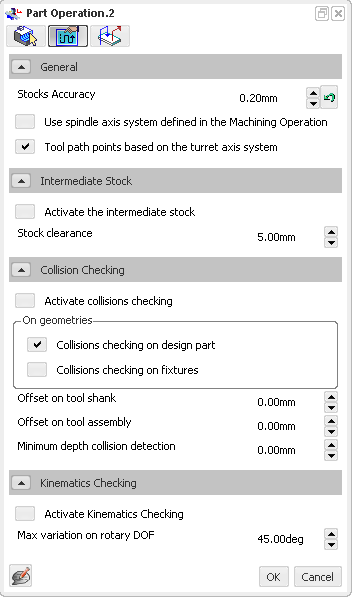
In General
- Define the value of the Stocks Accuracy.
The Stock Accuracy is the tolerance used to compute tessellations for photo/video simulations.
By default,
the Stock Accuracy is set to 0.2 mm. - Click
 to revert to the default value.
 - Select the required check boxes:
- Use Spindle Axis System
defined
in the Machining Operation: when selected, computes the tool
tip points based on
the spindle that is set on the Machining Operation.
If this check box is not selected,
the main spindle axis is used. This
is determined by the default reference
machining axis system set on the
Part Operation.
Note: You must select a multi-slide lathe machine or a mill-turn machine.
- Toolpath points based on the turret axis system: when selected, computes the tool path points shown in the Tool Path Replay dialog box and APT output based on the turret axis system for Lathe Operations.
By default,
this check box is cleared and the tool path points shown in Tool Path Replay dialog box and APT output are computed with respect to Part Operation axis system, in the spindle plane.
- Use Spindle Axis System
defined
in the Machining Operation: when selected, computes the tool
tip points based on
the spindle that is set on the Machining Operation.
If this check box is not selected,
the main spindle axis is used. This
is determined by the default reference
machining axis system set on the
Part Operation.
- Define the value of the Stocks Accuracy.
In Intermediate Stock
In Collision Checking
- Set the Minimum depth collision detection value.
Applying negative offsets on part surfaces or drive curves or surfaces leads to the detection of too many collisions, with the display of unwanted warnings. Setting the Minimum depth collision detection enables you to set a threshold under which collisions are not detected nor displayed. While Minimum depth collision detection has no maximum value, it cannot be greater than the tool corner radius defined in the Machining Operation.
By default,
these values are set to 0mm.
- Set the Minimum depth collision detection value.
In Kinematics Checking
- Define the value of the Max Variation on Rotary DOF.
By default,
the Max Variation on Rotary DOF is set to 45.00 deg.
- Define the value of the Max Variation on Rotary DOF.
Define the value of the Stocks Accuracy.
The Stock Accuracy is the tolerance used to compute tessellations for photo/video simulations.
By default,
the Stock Accuracy is set to 0.2 mm.Select the required check boxes:
- Use Spindle Axis System
defined
in the Machining Operation: when selected, computes the tool
tip points based on
the spindle that is set on the Machining Operation.
If this check box is not selected,
the main spindle axis is used. This
is determined by the default reference
machining axis system set on the
Part Operation.
Note: You must select a multi-slide lathe machine or a mill-turn machine.
- Toolpath points based on the turret axis system: when selected, computes the tool path points shown in theTool Path Replay dialog box and APT output based on the turret axis system for Lathe Operations.
By default,
this check box is cleared and the tool path points shown in Machining Operation dialog box and APT output are computed with respect to Part Operation axis system, in the spindle plane.
- Use Spindle Axis System
defined
in the Machining Operation: when selected, computes the tool
tip points based on
the spindle that is set on the Machining Operation.
If this check box is not selected,
the main spindle axis is used. This
is determined by the default reference
machining axis system set on the
Part Operation.
 .
.![]()
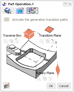
Activate the Generation of Transition Paths
Except for a mill-turn or a lathe machine, you can activate the generation of transition paths from the Transition Path tab.
Select the Activate the generation Transition Paths check box.
The icons used to specify the required geometry become available.
Note: When the check box Generate Transition Path
- is selected, the Manufacturing Program contextual menu items Generate Machine Rotations and Delete Generated Machine Rotations are not available. All the generated machine rotations are removed from the Activities Process Tree.
- is cleared, the Manufacturing Program contextual menu items Generate Machine Rotations and Delete Generated Machine Rotations are available .
- See Inserting Machine Rotations.