Inserting Machining Axis Changes

You can create a new Machining Axis System in theauthoring window.

  1. Open an existing Machining Process containing Machining Operations.

    1. Click NC Machine Control.
    2. Click Machining Axis Change in the toolbar that is displayed.

    The Machining Axis Change dialog box opens at the Geometry tab .

    By default,

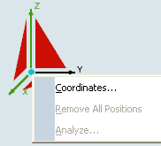
    • the X and Z axis are set to the corresponding directions of the absolute axis system. They are thus already defined and displayed in green.
    • an Axis Name is proposed.

    The sensitive icon in the dialog box lets you define a new Machining Axis System by defining an origin and new axis orientations.

  2. If required, edit the proposed Axis name field.

    This name is displayed beside the Machining Axis System in the authoring window.

  3. To define the origin of the new Machining Axis System, click the symbol representing the origin in the sensitive icon, then select a point or a circle in the authoring window. Alternatively, you can specify a point by means of its coordinates as follows:

    1. Right-click the symbol representing the origin in the sensitive icon.
    2. Select the Coordinates in its contextual command.

    3. Enter the point coordinates in the dialog box that appears.

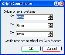
      Coordinates are expressed in the absolute axis system.

  4. Click one of the axes in the sensitive icon to specify the orientation of that axis in the dialog box that appears.

    The operating mode is the same as the one described in Defining the Tool Axis.

    1. Repeat this step for the second axis to define.

    Note: Since the Z axis is the privileged axis, we recommend that you define it first, then specify the X axis. The XY plane is perpendicular to the Z axis.The specified origin along with the X and Z axes thus are sufficient to define the Machining Axis System.

  5. Alternatively:

    1. Click one or the triangular areas in the sensitive icon.
    2. Select an existing axis system.
    3. Click the origin symbol in the sensitive icon.
    4. Select a point in the authoring window to position this axis system.

  6. To analyze the geometry referenced by a Machining Axis System, right-click any sensitive area in the dialog box and select Analyze in the contextual menu.

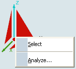
    The contextual menu items vary depending on the element selected.

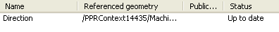
    The Geometry Analyser dialog box is displayed.

  7. To specify an origin statement in the NC data output, select the Origin check box.

    1. Optional: Depending on the machine type, specify an origin Number and Group.

    For an origin with coordinates (0,0,0) and origin number and group both equal to 1, this results in the following type of output syntax:

    $$*CATIA0 
             $$Origin.1 
             $$ 1.00000 0.00000 0.00000 0.00000	
             $$ 0.00000 1.00000 0.00000 0.00000	
             $$ 0.00000 0.00000 1.00000 0.00000
             ORIGIN/ 0.00000,0.00000,0.00000, 1, 1

  8. Go to the Syntax tab .

    1. Select the Initialize from PP words table check box to consult the Machining Axis Change syntax defined in the PP table referenced by the Part Operation. See Working with Generic Machine Editor.
    2. Or key in your own PP instruction for the Machining Axis Change. See Defining User Parameters in PP Instructions.

      Note: This user-defined syntax has no link with the PP table and its validity is not checked by Machine Programming.

  9. Click OK to create the new Machining Axis System in the authoring window


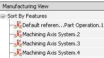
    • Machining Axis Systems are listed in the Manufacturing View.

    • A Machining Axis Systems can be shared by several Machining Axis Change operations.

    Note:

    • Machining Axis Changes do not impact the check reachability or table rotation functionalities. Similarly, the machine simulation is based on the toolpath and is not impacted by Machining Axis Changes.
    • When table rotations are computed, the solution is provided with the least (that is, optimized) rotation.

Important:
  • Output coordinates are computed in the current machining axis system as shown in the example below.

    The tool path is computed in the Machining Axis System AXS1 with origin (0,0,0):

    $$*CATIA0
             $$*AXS1 
             $$ 1.00000 0.00000 0.00000 0.00000 
             $$ 0.00000 1.00000 0.00000 0.00000
             $$ 0.00000 0.00000 1.00000 0.00000
             GOTO/ -40.00000, -30.00000, 20.00000
             GOTO/ -40.00000, 30.00000, 20.00000

    The same tool path is computed in the Machining Axis System AXS2 with origin (0,0,20):

    $$*CATIA0
             $$*AXS2
             $$ 1.00000 0.00000 0.00000 0.00000
             $$ 0.00000 1.00000 0.00000 0.00000
             $$ 0.00000 0.00000 1.00000 20.00000
             GOTO/ -40.00000, -30.00000, 0.00000
             GOTO/ -40.00000, 30.00000, 0.00000