About NC Manufacturing Verification | ||
| ||
Access to NC Manufacturing Verification
NC Manufacturing Verification appears as a dialog box when you click Tool Path Replay.
- the Machining Operation dialog box,
- the West Compass toolbar,
- the Activities Process Tree Contextual Menus.
The dialog box is referred to as the Tool Path Replay dialog box in the documentation. 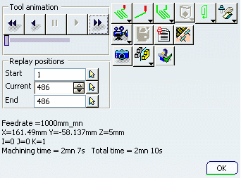
Note:
- The title of the dialog box takes the name of the current Machining Operation.
- If a Profile Contouring operation was created with the cutter profile output option, both the cutter profile and tip trajectory can be displayed in the replay.
![]()
Replay Tool Path
Replaying a tool path allows you to check its quality.
Partial Tool Path Replay Behavior
A partial Tool Path Replay is defined by the Start, Current, and End Replay positions and is updated according to your inputs.
Partial Tool Path Replay:
- can be used for a single Machining Operation. Replay on Manufacturing Program is also possible and the partial replay positions are for the current Machining Operation being replayed. The inputs can be given with respect to the current Machining Operation by pausing the replay on Manufacturing Program.
- is not available for multiple Machining Operations or auxiliary operations like Tool Change, Transition Path, COPY Operator, Machine Rotation, and material removal simulation. For any unsupported activity, the replay positions are grayed out.
- is not available in Plane by Plane, Feedrate by Feedrate, and By Sectioning modes. If you switch to one of these modes, the positions are restored to full tool path and the editor boxes are grayed out. The behavior of these replay modes is then the same as for the complete tool path.
Visualization mode and color modes can be specified for partial Tool Path Replay.
During continuous replay of partial tool path, the Current position spinner box is grayed out and once the replay is completed, the spinner box is updated with the Current position of the tool.
Collision Checking
If the Activate Collisions Checking check box is selected (see Creating a Part Operation), the points and areas in collision are displayed.
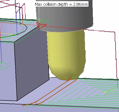
When you move the cursor onto a collision point, the maximum collision depth and the intersection between the tool and the part are shown.
Collisions checks are done at each point and between points of the tool
path.
- If the tool is in collision at a point of the tool path, a red cross is displayed at that point.
- If the tool is in collision on at least a part of a segment of the tool path, the whole segment is displayed in red and a red cross is displayed at the end point (the intersection between the tool and the part is not displayed in this case).
For the update mechanism:
- If the user representation is modified inside a V6 session, the modification will not be recognized and the collision checking will not be automatically re-computed. You must force the computation of the operation using the tool.
- Example of scenario to avoid inside the same session:
- the tool path is replayed with collision checking active on an operation linked to a tool having a user representation => OK,
- the user representation is modified => OK,
- the tool path is replayed again => KO since the collision checking is not automatically re-computed.
Transition Paths between Operations
A Transition Path from Machining Operation A to Machining Operation B is represented by a
dashed line. Its color depends on the feedrate. This feedrate depends on
whether a clearance macro is present:
- If a clearance macro is activated on Machining Operation B, the feedrate of the clearance path is used for the Transition Path.
- If no clearance macro is activated on Machining Operation B, the feedrate depends
on the setting of the Set Rapid feedrate at start of operations
option in the Generate
NC Output Interactively dialog box (See NC Data Options):
- If the check box Set Rapid feedrate at start of operations is selected, a RAPID feedrate (red) is used for the Transition Path.
Note: If Machining Operation B is an axial Machining Operation, the feedrate is always set to RAPID.
- If the check box Set Rapid feedrate at start of operations is not selected, the first feedrate defined on Machining Operation
B is used for the Transition Path (for example, yellow for approach
or green for machining).
Note: If Machining Operation B is an axial Machining Operation, the feedrate is always set to RAPID.
- If the check box Set Rapid feedrate at start of operations is selected, a RAPID feedrate (red) is used for the Transition Path.
Color Coding after APT Import
When the Tool Path Replay is done on a Machining Operation after an APT
Import, the color feedrate codes are not respected, because no information is provided about the tool path type (approach, machining , retract,
and so on) in the APT file.
In this case:
- the machining feedrate color is assigned to the tool path with the smallest feedrate value,
- the approach feedrate color is assigned to the tool path with next higher feedrate value,
- the retract feedrate color is assigned to the tool path with the next higher feedrate.
Influence of the Hide/Show Status of Selected Elements
The following rules summarize the tool path computation behavior depending
on the Hide/Show status of selected elements.
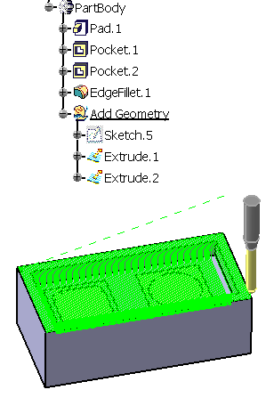
- Rule 1: If you select a Body or OpenBody, and use it as Part, Check or
Fixture in a Machining Operation, the tool path uses the Body or OpenBody,
regardless of whether it is in Show or Hide status. In the example below, the Body is selected as the part in a Sweeping
operation.
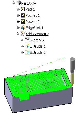
- Rule 2: If you select a Body or OpenBody, and use faces (which are sub-elements
of this Body or OpenBody) as Part, Check or Fixture in a Machining Operation, only the sub-elements which are in Show status are used during
the tool path computation. Hidden sub-elements are ignored in the computation. In this example, Extrude 2 is ignored in the tool path computation.
- Rule 3: If you select explicitly a set of faces and use them as Part, Check or Fixture in a Machining Operation, the tool path uses these faces, regardless of whether they are in Show or Hide status.
Influence of the Faces Selection Mode
By boundary of faces allows you to select a surface from the PPR tree while By belt of faces allows only the selection from the authoring window, because:
- In all cases, the tool path computation algorithm supports only a contour of edges, which is retrieved from the selected faces.
- This contour is not created by the same way with By belt of faces or By boundary of faces.
- By boundary of faces
- The edge contour is the external boundary of selected faces. However, all faces must be topologically connex (they share their adjacent edges). The edges used by the tool path computation algorithm exist in the design.
- By belt of faces
- This situation is more complex because:
- The contour must be a belt of faces: each face must be adjacent to only one other face of the belt (except one if the contour is closed).
- The faces must be ruled only the same axis (tool axis)
- The faces must be topologically adjacent
- The order of the faces contribute to the stability of the material side in the case where the belt of face is not closed (for Profile Contouring).
The edges used by the tool path computation algorithm do not exist in the design. To get the contour of edges and to get the boundary of faces, it is projected onto the bottom plane of the bounding box of the belt, and wireframe elements are deleted including free vertices.
When you select an object in the PPR tree, you do not select the faces but the complete feature whose result can include more than one face. Those faces are not necessary built as a belt of faces. Moreover, the number and position of the faces included in the feature can be modified by you. In this case, it may not be possible to compute the Machining Operation.
![]()
Material Removal Simulation in Photo Mode
You can simulate the material removed by Machining Operations in Photo mode.
- Photo Mode with Any Fixed Axis
- Photo simulation is possible along
any fixed axis.
This means that you can simulate Machining Operations (MO) whose tool axis
is different from the Z-axis of the Part Operation machining axis system:
- Case 1:
All Machining Operations have a constant identical axis not equal to the Setup Z-axis. The
Photo simulation can be done on any or all of these Machining Operations.
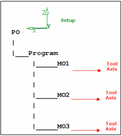
- Case 2:
All Machining Operations have constant but different axes, not equal to the Setup Z-axis.
The Photo simulation can be done on any of these Machining Operations.
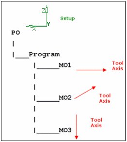
- Case 1:
All Machining Operations have a constant identical axis not equal to the Setup Z-axis. The
Photo simulation can be done on any or all of these Machining Operations.
- Unsupported Entities
-
- Turning operations and multi-axis Machining Operations cannot be simulated in Photo mode.
- The Photo simulation can be done on the first Machining Operation previous to the selected Machining Operation (going from the selected Machining Operation to the Part Operation) that has a non-changing tool axis.
- Boring Bars, T-Slotters, and Two Sides Chamfering tools are not supported.
- Check surfaces are not taken into account in Photo mode.
- If you select a Body (which may be in Show or Hide mode) as Stock, Design, or Fixture then only sub-elements of the Body that are in Show mode can be used during material removal simulation. Hidden sub-elements can be ignored in the simulation. In the case of the Stock, if all the elements are hidden then the Stock envelope is displayed for the simulation.
- Program Limitations
- When a Photo mode analysis is performed on vertical walls (walls parallel to the Z-axis of the Part Operation machining axis system), the results of the analysis such as Pick Point Information, Analysis, and Faults cannot be accurate.
- Any concavity details in the stock is filled out.
Only the details on the machined surface is shown and the surface boundary
is extruded to show the entire stock.
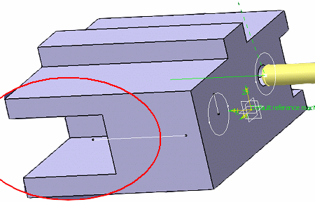
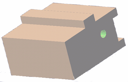
![]()
Material Removal Simulation in Video Mode
You can simulate the material removed by Machining Operations in video mode.
Stock, Design, and Fixtures for Material Removal Simulation
The following can be defined as stock, design, or fixtures in the Part Operation editor:
- Part bodies
- Hybrid bodies
- Cloud of points bodies
Video results can be used effectively in a Part Operation that contains more that one Manufacturing Program. The video result of the last Machining Operation of a Manufacturing Program can be used as the stock for a following Manufacturing Program. For that, you must select the Simulation at Part Operation level option and use the Video from Last Saved Result command when using simulation in the following Manufacturing Program.
If there is no stock defined, the envelope volume of the design part is used. If there is no design part, the envelope volume of the design part is used.
In video mode only, if the stock geometry is not correctly closed, a stock representing the envelope volume of the stock is computed.
Video Results
- The Remove Video Result contextual command on a Machining Operation removes the video result associated to that Machining Operation. In this case, the status of the Video Result column of the Activities Process Tree changes from Yes to No for the Machining Operation.
- The Remove Video Result contextual command on a Manufacturing Program removes all the saved material removal simulation videos
from the Manufacturing Program
Note: A video result may become incoherent if Machining Operations used in its creation are modified. Incoherent video results should be removed by you.
Video Behavior for Circular Arcs
![]() By default,
wherever there are arc segments in the tool path, circular arc commands
are given as input for the video simulation. In this case, there are no intermediate interpolated points where the
video can be stopped.
By default,
wherever there are arc segments in the tool path, circular arc commands
are given as input for the video simulation. In this case, there are no intermediate interpolated points where the
video can be stopped.
Running one step of the video can simulate machining of the arc segment.
To see the intermediate interpolated points (running one step), the 2D circular interpol check box must be cleared in the Numerical Control tab of the Machine dialog box. See Working with Generic Machine Editor.
Tool Holder Behavior
In video simulation, the holder component of a tool-holder assembly also
cuts material of stock and/or fixture. The behavior depends on the collision detection setting in the
Photo/Video tab:
- When Collision detection is set to Ignore, detection is de-activated: the holder cuts material and no color is set, even when there are valid collisions of holder.
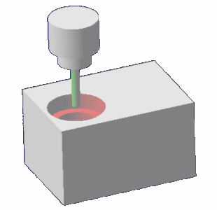
- When Collision detection is set to Stop or Continue, detection is activated: the holder cuts material and the cut material is displayed in red to indicate collision.
Example of a Circular Milling operation with default End Mill with 2-stage
holder defined: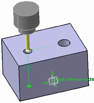
- The material is cut by the holder due to nature of the tool path and the interaction between the tool-holder assembly and the stock.
- Video simulation with Collision detection set to Ignore:
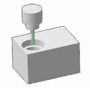
- Video simulation with Collision detection set to Stop
or Continue:
Miscellaneous
- Performance
- Reduced video simulation performances may be experienced when a non-cutting diameter is specified on an end mill or a face mill. To improve video performances, if possible, try setting the value of this parameter to zero.
- Minimum Discretization Step
- The minimum discretization step that is set in the Generic Machine dialog box (see Working with Generic Machine Editor) affects
the quality of the video simulation:
- With a large discretization step, consecutive tool points may be ignored and so some portions of the tool path may be removed during the video simulation.
- In general, the greater the discretization step, the coarser the video simulation.
- Sub-elements in Hide/Show
- The material removal simulation takes only the visible sub-elements of Bodies selected as Stock, Design, or Fixture into account.
- Collision Checking
- Boring Bars and Two Sides Chamfering tools are not collision checked in video mode.
- TRACUT Display Mode
- During the Tool Path Replay, before getting into the video simulation mode, select the desired option TRACUT ON or TRACUT OFF that you want to see in the video simulation. You cannot change the TRACUT ON/OFF selection during the video simulation.